KIN_TYP_18
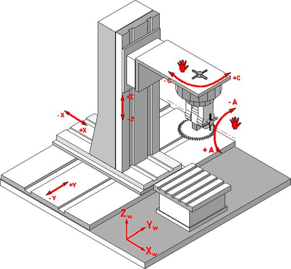
The kinematic structure consists of three translatory NC axes. In addition, there are rotary axes which can manually be set. These axes cannot be addressed from the NC program.
Axis configuration in NC channel | ||
Axis designation | X, Y, Z | |
Axis index | 0, 1, 2 | |
Kinematic structure | ||
| Tool axes | Workpiece axes |
NC axes | X, Y, Z | - |
Auxiliary axes | C, A | - |

Offset data of the kinematic structure:
HD offset | param[i] | Description |
|---|---|---|
HD2 | 1 | Y Axis offset from tool holding device to rotation point of A Axis (auxiliary) |
HD3 | 2 | Z axis offset rotation point of A axis to tool reference point |
HD4 | 3 | Fixed angle for manual auxiliary A axis |
HD5 | 4 | Fixed angle for manual auxiliary C axis |
HD7 | 6 | Static tool offset in X |
HD8 | 7 | Static tool offset in Y |