KIN_TYP_11
The kinematic structure consists of three translatory cartesian axes and two rotary axes. As a peculiarity, the machine features the slanting B axis.
Axis configuration in NC channel | ||
Axis designation | X, Y, Z, A, B | |
Axis index | 0, 1, 2, 3, 4 | |
Kinematic structure | ||
| Tool axes | Workpiece axes |
NC axes | X, Y, B | Z, A |
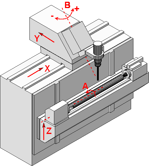
The design of the slanting B axis is the most striking feature of the kinematic structure. If the tool length is selected such that the TCP (tool centre point) lies exactly on the extension of the B axis, compensation movements in the translatory axes are not necessary when the tool orientation via the B axis changes (compensation movements due to changes in the A axis orientation are always necessary). If the selected tool length is not ideal (i.e. if the TCP is not exactly on the extension of the B axis), there are minor additional compensation movements on the linear axes that depend on the deviation from the ideal length.
Due to the design of the B axis, there can be no singular points in the backward transformation of the orientation axes. On the other hand, not all tool orientations can be selected (see below).
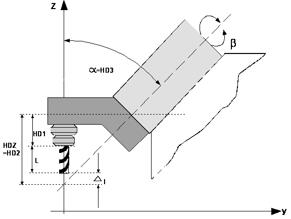
The home positions of the machine axes XM, YM, ZM are selected such that the fictitious extensions of AM und BM intersect. The home position of BM is selected such that the tool is in a vertical position and, consequently, parallel to Z0 if bM=0 Figure 2-13 shows the home position of BM). The home position of AM should expediently be selected such that the Y0, Z0 workpiece axes run in parallel to the directions of the machine axes.
HDZ represents the ideal tool length as a geometry parameter of the kinematic machine structure. HD1 represents the first tool head parameter, and L represents the actual tool length (cutter length).
Please note that l is a signed value and may therefore be negative.
Offset data of the kinematic structure:
HD offset | param[i] | Description |
|---|---|---|
HD1 | 0 | Z axis offset tool holding device to tool reference point |
HD2 | 1 | Ideal tool length |
HD3 | 2 | Angle beetween rotation axis B and A |