KIN_TYP_6
The kinematic structure consists of three translatory axes and one rotary axis in the tool. As a peculiarity, the tool of this kinematic structure points in the positive Z direction.
Axis configuration in NC channel | ||
Axis designation | X, Y, Z, C | |
Axis index | 0, 1, 2, 3 | |
Kinematic structure | ||
| Tool axes | Workpiece axes |
NC axes | X, Y, Z, C | - |
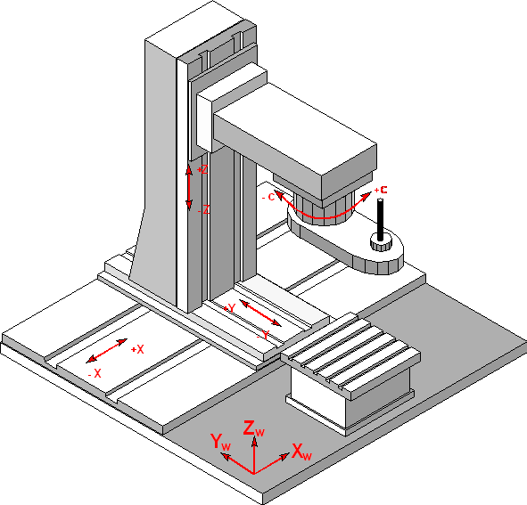
The axes are arranged in the sense of a right-handed system. The home position of the C axis is in the positive direction of the Y axis.
The automatic orientation setting of the 4-axis tool head with manually adjustable A axis depends on the position of the A axis. If the physical machine axis position and the value in the HD parameter of the A axis do not agree, correct automatic alignment is not possible.
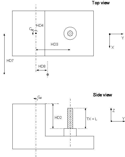
Offset data of the kinematic structure:
HD offset | param[i] | Description |
|---|---|---|
HD1 | 0 | Z Axis offset from tool holding device to rotation point of A axis (auxiliary) |
HD2 | 1 | Z axis offset of tool holding device to rotation point of C axis |
HD3 | 2 | Fixed angle for manual auxiliary A axis |
HD4 | 3 | Rotation offset of C axis |
HD5 | 4 | Y offset rotation axis A to rotation axis C |
HD6 | 5 | X offset from to tool reference point rotation to rotation point of C axis |
HD7 | 6 | Static tool offset in X |
HD8 | 7 | Static tool offset in Y |