KIN_TYP_3, KIN_TYP_4
The kinematic structure of the machine consists of three translatory axes and one rotary axis in the tool (double spindle head).
Axis configuration in NC channel | ||
Axis designation | X, Y, Z, B | |
Axis index | 0, 1, 2, 3 | |
Kinematic structure | ||
| Tool axes | Workpiece axes |
NC axes | X, Y, Z, B | - |
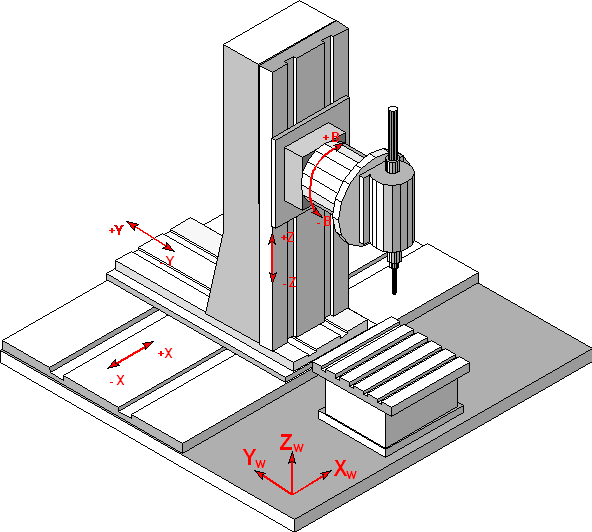
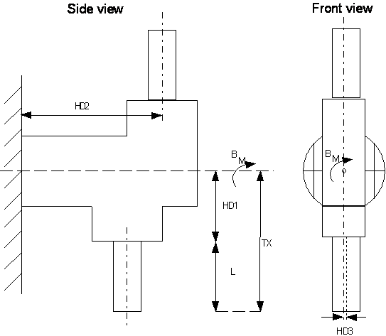
Figure 2-4 shows the structure of the milling head for the zero position of the B axis. It features two spindles (referred to in this document as top and bottom spindle, irrespective of the current position of the B axis) so that two tools may be clamped that are rotated by 180° against each other.
The selection of the currently active spindle and/or tool should be possible through a command in the NC program.
If the top spindle is active, the programmed value for the B axis must be modified as follows:

Thus, changing spindles means rotating the B axis through an angle of 180° and, caused by the geometry constants with active RTCP, translating all three linear axes.
Offset data of the kinematic structure:
HD offset | param[i] | Description |
|---|---|---|
HD1 | 0 | X Axis offset from tool holding device to rotation point of C Axis |
HD2 | 1 | Y Offset from rotation point of C axis to reference point for tool 1 and 2 |
HD3 | 2 | X Offset from rotation point of C axis to reference point for tool 3 and 4 |
HD4 | 3 | Z axis offset of tool holding device |
HD5 | 4 | Rotation offset of C axis |
HD7 | 6 | Static tool offset in X |
HD8 | 7 | Static tool offset in Y |