KIN_TYP_1
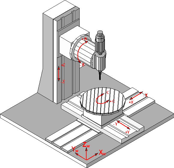
The kinematic structure of this machine consists of two translatory axes and one rotary axis in the workpiece, and one translatory axis and one rotary axis in the tool.
Axis configuration in NC channel | ||
Axis designation | X,Y, Z, B, C | |
Axis index | 0, 1, 2, 3, 4 | |
Kinematic structure | ||
| Tool axes | Workpiece axes |
NC axes | Z, B | X, Y, C |
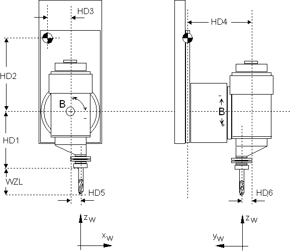
Here, you need the geometry constants HD1 and HD2. Figure 2-2 shows the correlation.
The rotation of the workpiece table rotates the workpiece coordinate system, but not the machine coordinate system.
Offset data of the kinematic structure:
HD offset | param[i] | Description |
|---|---|---|
HD1 | 0 | Z offset tool holding device to rotation point B axis |
HD2 | 1 | Z offset rotation point B-axis to reference point tool slide |
HD3 | 2 | X offset reference point tool slide to rotation point B axis |
HD4 | 3 | Y offset reference point tool slide to rotation point B axis |
HD5 | 4 | X offset rotation point B axis to tool holding device |
HD6 | 5 | Y offset rotation point B axis to tool holding device |
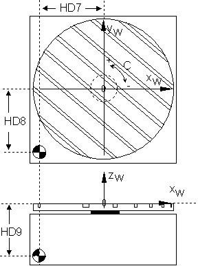
HD7 | 6 | X offset machine origin MNP to rotary axis C |
HD8 | 7 | Y offset machine origin MNP to rotary axis C |
HD9 | 8 | Z offset machine origin MNP to rotary axis C |
HD13 | 12 | Rotation direction B axis (*), 0: negative, 1positive |
HD14 | 13 | Rotation direction C axis, 0 positive, 1 negative |
(*) The rotation direction of the B axis is mathematically negative.