Organisation of the HLI
Unlike the simple structuring of the data to be exchanged in input/output data conventional with PLC applications, the HLI contains complex structures. These reflect the logical structuring of the CNC into channels, axes and plattform data.
The logical structure of the HLI is outlined in the diagram below:
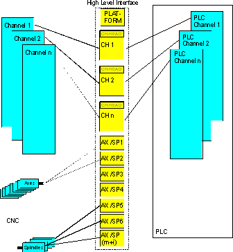 Fig.2: Figure 0.2: Structuring of the HLI
The structuring into channel-specific and axis-specific data areas is clearly shown. The channel-specific and axis-specific memory areas on the HLI feature the same logical structure.
The relevant memory areas are subdivided into
- a header area with management data
- and a user data area with status information, control commands and technology data.
The channel/axis-specific memory areas are shown magnified in the diagram below.
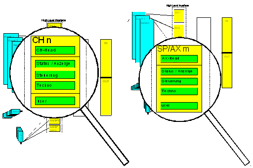 Fig.3: Figure 0.3: Data of a channel \ of an axis
A distinction is made between the following data areas, whereby channels and axes may be considered the same:
The header areas contain
- management data such as version information and log-on information
The user data areas contain
- status and display information (CNC → PLC),
- control interfaces (PLC → CNC),
- technology areas (CNC → PLC and PLC → CNC),
- and any application-specific data.
Specific data, such as status information, is updated cyclically by the CNC and can be read by the PLC if needed. M functions, so-called usage information, must, however, be read by the PLC. For this purpose, the interface contains suitable mechanisms ensuring that no data is lost and that the order of the data is retained.