Project File Builder
The Project File Builder generates a Building Automation Manager project from an OOXML (Office Open XML) table.
Under the menu item Tools → Extensions... the Project File Builder can be called up in the subsequent selection dialog.
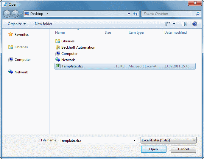
The familiar Windows dialog for opening files appears, in which the required *.xlsx file can be selected. Press the Open button to start processing the table. Once the process is complete, all windows can be closed until the main window of the BA Manager is shown again.
 | Importing an OOXML table results in creation of a new project! An existing project cannot be extended. |
Creating the table
Successful reading of the OOXML table requires a valid structure. This includes defined column and worksheet labels and table entries.
Controller worksheet
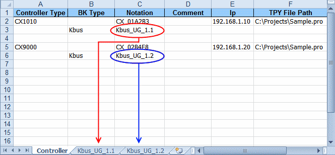
The first worksheet defines the controllers used. It must be called Controller. As indicated in the diagram, each controller is defined by at least 2 lines.
The first line contains:
- Controller Type: Indicates the controller type.
- Valid controller types:
- CX1000
- CX1010
- CX1020
- CX1030
- CX5000
- CX9000
- CX9001
- CX9010
- CX9020
- IpcCpX86
- IpcCpArm
- Notation: Name of the controller.
- Comment: Comment (optional).
- Ip: IP address (valid IPv4) of the controller (not for KBUS).
- TPY File Path: Path to the PLC project for obtaining the *.tpy file.
The second line contains:
- BK Type: Indicates the Bus Coupler type. The permitted value is KBUS (only CX devices). It goes without saying that the controller type must support the specified Bus Coupler type. Please refer to the relevant documentation.
- Notation: Name of the Bus Coupler and the worksheet. These names must be identical!
Bus Coupler worksheet
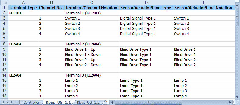
These worksheets contain the terminals, sensors, actuators and subsystems connected to the Bus Coupler. Each terminal is defined by a minimum of 2 lines. For channel-less terminals (e.g. end terminal KL9010) only the top line is required.
The first line contains:
- Terminal Type: terminal type.
- Terminal/Channel Notation: terminal name.
The second line contains:
- Channel No.:terminal channel to be linked.
- Terminal/Channel Notation: channel name.
- Sensor/Actuator/Line Type: type of sensor/actuator/subsystem to be created, with which the channel is subsequently linked (optional).
- Permitted sensor/actuator/subsystem types:
- DIGITAL SIGNAL TYPE 1 - 3
- ANALOG SIGNAL TYPE 1 - 3
- LAMP TYPE 1 - 3
- BLIND DRIVE TYPE 1 - 2
- WINDOW DRIVE TYPE 1
- VALVE ACTUATOR 2 POINT
- VALVE ACTUATOR 3 POINT
- VALVE ACTUATOR CONTINUOUS
- ENOCEAN LINE TYPE 1 - 2
- DALI LINE TYPE 1
- Sensor/Actuator/Line Notation: name of sensor/actuator/subsystem.
- Function: actuator parameters. Permitted values for
- LAMP TYPE 1
- DIGITAL
- ANALOG
- BLIND DRIVE TYPE 1
- UP
- DOWN
- WINDOW DRIVE TYPE 1 and VALVE ACTUATOR 3 POINT
- OPEN
- CLOSE
- Parameter 1 - 4: Additional parameters
Ensure that terminal channel, sensor/actuator/subsystem and the function, if applicable, are compatible. Linking a channel of an analog output terminal with a digital signal would not be permitted, for example.
A function must be defined if an element from type LAMP TYPE 1, BLIND DRIVE TYPE 1, WINDOW DRIVE TYPE 1 or VALVE ACTUATOR 3 POINT is to be defined.
Except for the element names the document is not case sensitive, and hyphenation is not taken into account. Entries such as EnOceanLineType1 or cx 9 0 0 0 are therefore also permitted, for example. You only have to list the terminal channels you actually want to use. Ensure that the listed channels exist.
For subsystems the first channel of the respective terminal should be linked with the corresponding subsystem line.
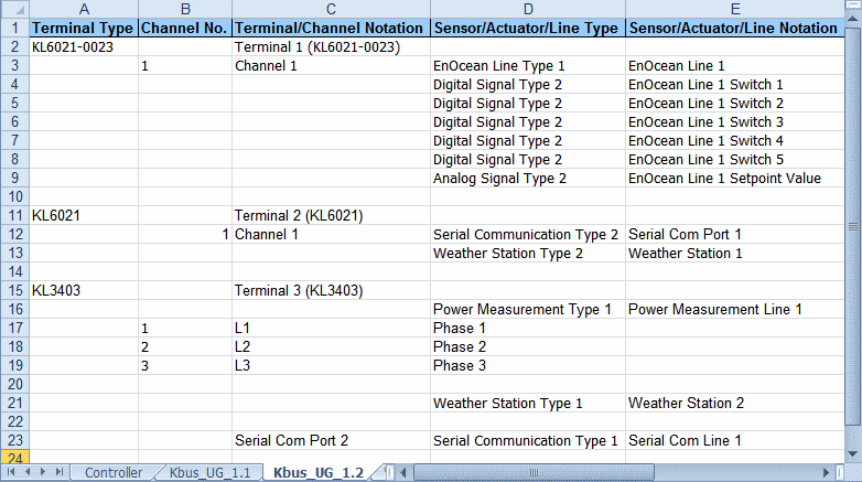
EnOcean
EnOcean modules can be defined at the same time. To this end add the required content in the following columns for each EnOcean module:
- Sensor/Actuator/Line Type: DIGITAL SIGNAL TYPE 1 or ANALOG SIGNAL TYPE 1.
- Sensor/Actuator/Line Notation: module name.
- Parameter 1: terminal ID.
- Parameter 2: transmitter ID of the module.
- Parameter 3: module type.
- Permitted values:
- PTM 100 (only for DIGITAL SIGNAL TYPE 1)
- PTM 200 (only for DIGITAL SIGNAL TYPE 1)
- PTM 250 (only for DIGITAL SIGNAL TYPE 1)
- STM 100
- STM 250
- Parameter 4: depends on the selected module type and describes the data byte and bit (for PTM modules therefore the rubber contact).
- Permitted values for PTM 100:
- STATE O / CHANNEL A
- STATE O / CHANNEL B
- STATE O / CHANNEL C
- STATE O / CHANNEL D
- STATE I / CHANNEL A
- STATE I / CHANNEL B
- STATE I / CHANNEL C
- STATE I / CHANNEL D
- Permitted values for PTM 200 and PTM 250:
- STATE O / CHANNEL A
- STATE O / CHANNEL B
- STATE I / CHANNEL A
- STATE I / CHANNEL B
- For STM 100 and STM 250 the data byte (low word) must
be set (value range: 0-3). Optionally, it can be followed by the
data bit (high word), separated by "." (value range:
0-7).
The meaning of these bits is described in the EnOcean documentation.
DALI
DALI lamps can also be defined at the same time. To this end add the required content in the following columns for each DALI lamp:
- Sensor/Actuator/Line Type: LAMP TYPE 2.
- Sensor/Actuator/Line Notation: lamp name.
- Parameter 1: DALI address of the lamp.
To speed up the process a template is available for download via the following link. This table contains the basic structure and a sample entry for each possible type.
 Template with sample entries for all types