Example: Linking of BinaryInput and BinaryOutput objects in the PLC program
The following example illustrates how the link of a binary input with a binary output can be realized with the aid of BACnet objects and a PLC program. The procedure is based on PLC automapping.
Summary:
- A binary input, represented by the BACnet object "BI_0", is to write its Present Value to the binary output, represented by the BACnet object "BO_0", with priority "12", if the object "BI_0" is not in state OutOfService
- If the object "BI_0" is in state OutOfService, PresentValue access with priority "12" to object "BO_0" should be deleted.
 The example bi_bo_example.zip can be downloaded from here.
The strategy is explained step-by-step with the aid of screenshots (For creating servers and objects see also examples "Create BACnet adapters and servers" and "Manual linking of hardware (terminal), BACnet BinaryInput and PLC program"):
- Create BACnet adapters and servers (see Example "Create BACnet adapters and servers")
- Creating an I/O bus (K-bus, E-bus, BK90xx)
- Execute I/O automapping of the bus on BACnet (see "example: I/O automapping")
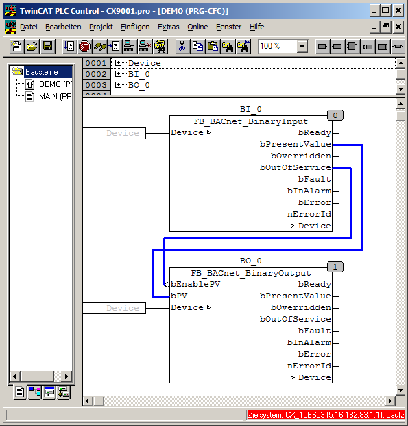
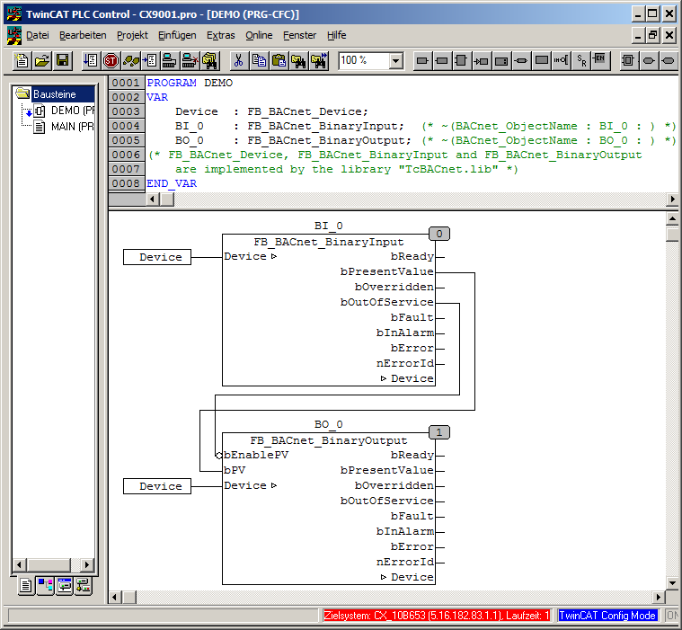
- Creating a PLC project and inserting object instances (The link to the input/output objects is realized using the object names "BI_0" and "BO_0" in the comment, see also "PLC automapping"):
- Adding the PLC project (.tpy) to the System Manager configuration:
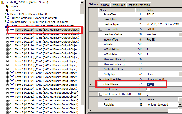
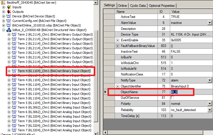
- Important: To ensure correct linking, the object names should correspond to the PLC comment (assignment using the object ID would also be possible):
- a) Binary output "BinaryOutput: 0" is to be linked with the PLC instance "BO_0":
- b) Binary input "BinaryInput: 0" is to be linked with the PLC instance "BI_0":
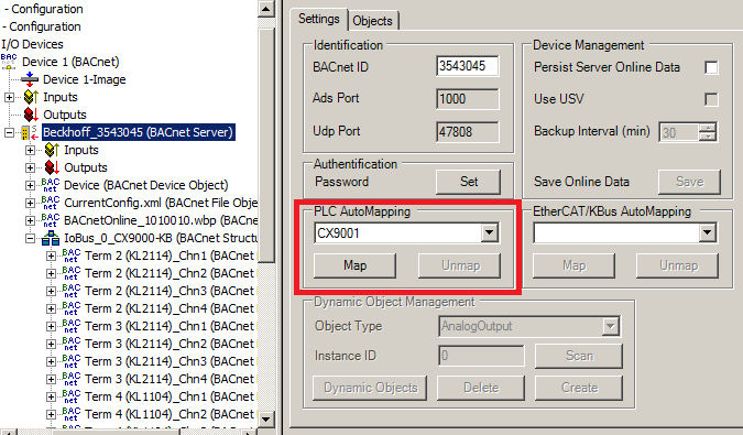
- Execute PLC automapping via the Settings tab of the BACnet server:
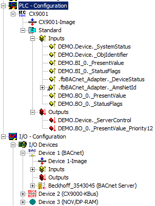
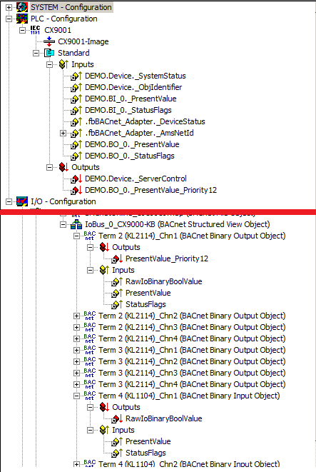
- The process data of the BACnet objects and the corresponding data of the PLC program are then linked:
- The configuration has to be activated (Ctrl+Shift-F4), and the PLC program has to be loaded (PLC Control via menu "Online --> Login" or F11). The PLC is then switched to Run state with F5 or "Online --> Start".
- The different PLC states and the corresponding BACnet properties are described below:
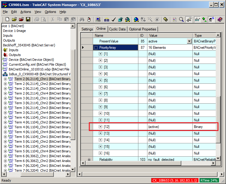
- a) Case 1: "BI_0" is not OutOfService and ACTIVE or INACTIVE → Priority "12" of "BO_0" is set to ACTIVE or INACTIVE and acts on the hardware terminal:

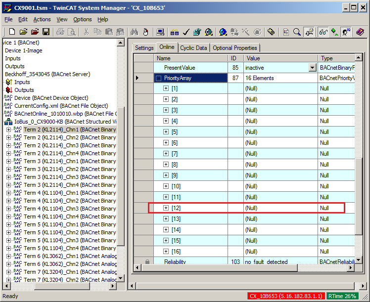
- b) Case 2: "BI_0" is OutOfService → Priority "12" of "BO_0" is deleted (Zero) and the value from property RelinquishDefault of "BO_0" acts on the hardware terminal: