Example: Manual linking of hardware (terminal), BACnet BinaryInput and PLC program
The following example describes the linking of two digital inputs with the corresponding objects and the PLC.
- Create a BACnet adapter and server (see "Example: Create BACnet adapters and servers")
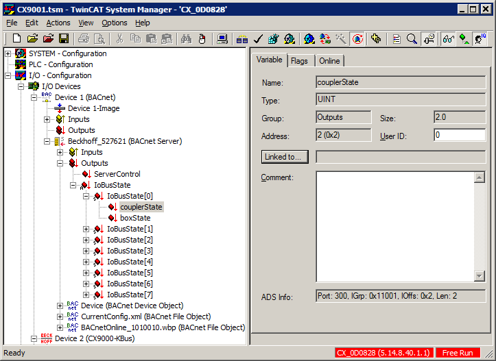
- Link the state of the bus coupler under which the hardware terminal was added with the BACnet server
- a) Right-click on couplerState
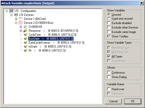
- b) In the subsequent dialog select BusState of the bus coupler selected (ATTENTION: deselect "Exclude other Devices" and "Exclude same Image" and select "All Types") and confirm with "OK"
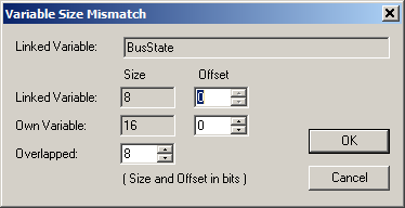
- c) Confirm the subsequent dialog with "OK"
- The first BinaryInput object under the previously created BACnet server is now added
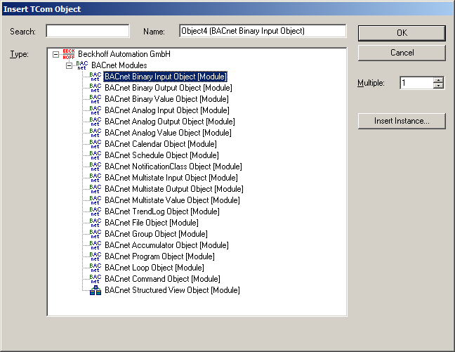
- a) Right-click on the BACnet server and select "Append Object..."
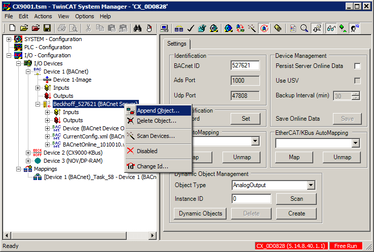
- b) In the subsequent dialog select the module "BACnet Binary Input Object" and confirm with "OK"
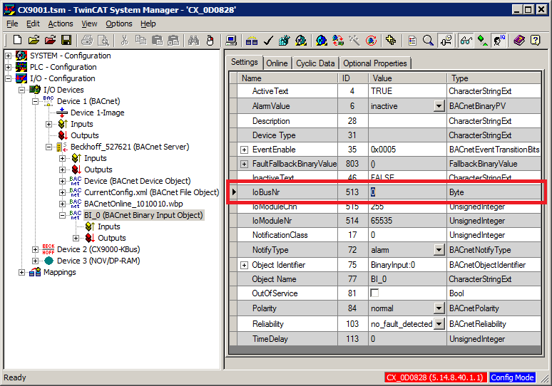
- For setting the property "Reliability" of the BinaryInput object the bus number of the bus state linked under 2 above has to be set in the BACnet object (bus index "0"):
- For subsequent mapping onto the PLC the corresponding properties should be added to the cyclic I/O mapping. To this end the following properties should be selected as a minimum:
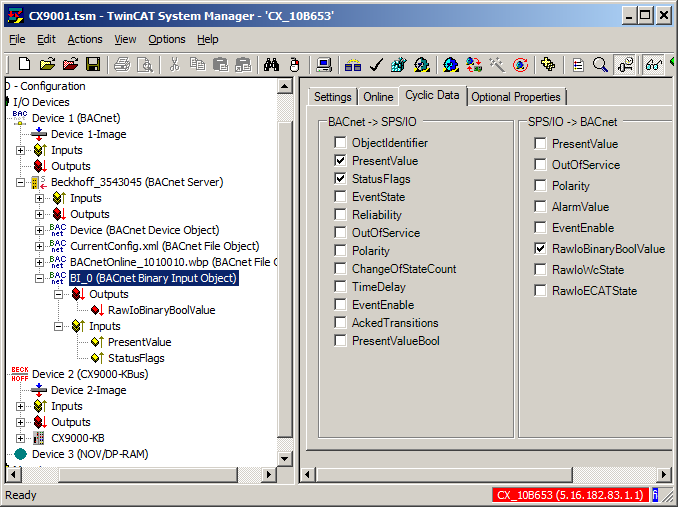
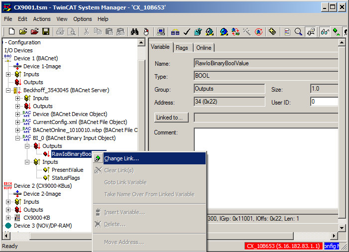
- Subsequently the link between the hardware terminal and the BACnet object is created. To this end RawIoBinaryBoolValue has to be linked with the corresponding bit of the hardware terminal:
- a) Right-click on RawIoBinaryBoolValue under the BACnet object "BI_0" and select "Change Link..."
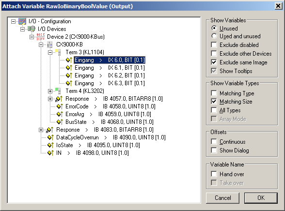
- b) In the subsequent dialog select the symbol "Input" of the corresponding hardware terminal (ATTENTION: deselect "Exclude other Devices" and "Exclude same Image" and select "Matching Size") and confirm with "OK"
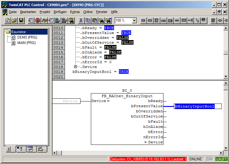
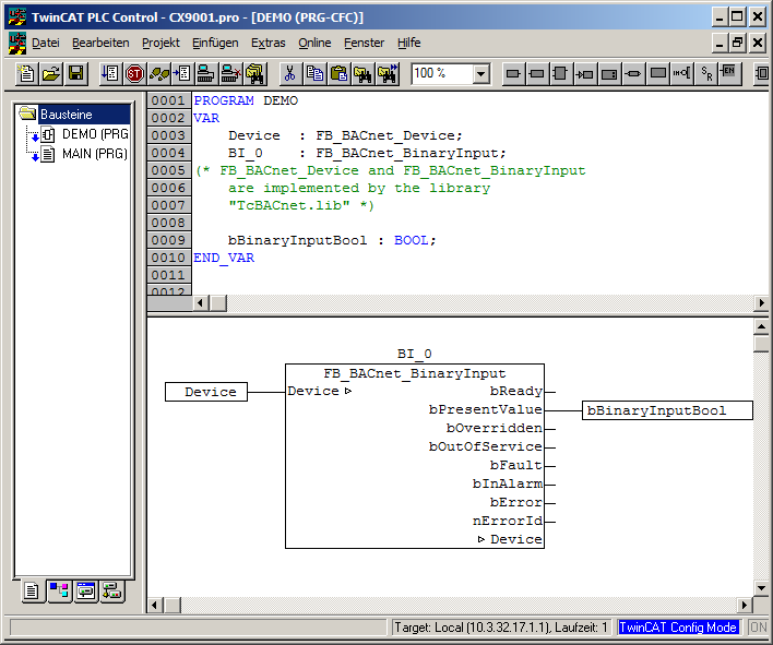
- The library "TcBACnet.lib" can be used for accessing BACnet objects from a PLC runtime. It makes all objects available as function blocks with the corresponding I/O points for the mapping in the System Manager. In the following example a PLC project with an instance of the function "FB_BACnet_BinaryInput" with name "BI_0" is created. The function is inserted into the PLC program "DEMO" as follows (The "DEMO" program is in turn called in the "MAIN" program. Program "MAIN" is added to the task configuration as a task). The function block instance "Device" enables access to the device object and the server state and has to be transferred to the function block instance "BI_0":
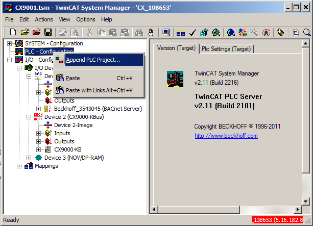
- Once the PLC project is compiled it has to be made available in the System Manager. Right-click on the symbol "PLC - Configuration". Afterwards by means of "Append PLC Project..." add the TPY file of the previously compiled PLC project:
- Once the PLC project has been added, all I/O variables of the PLC program are available in the System Manager. The global instance "fbBACnet_Adapter" of type FB_BACnet_Adapter is available in each PLC project linked via the library "TcBACnet.lib". It is used for accessing the BACnet network adapter, its AMS NetID and the link status. The I/O variables under the instance now have to be linked with the I/O points of the BACnet adapter:
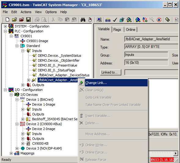
- a) Right-click on the symbol ".fbBACnet_adapter._AmsNetID" and select "Change Link..."
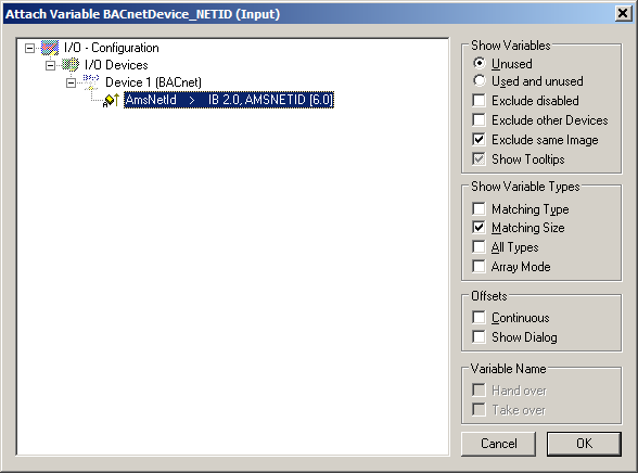
- b) In the subsequent dialog select the AmsNetID of the BACnet device (ATTENTION: deselect "Exclude other Devices" and select "Matching Size") and confirm with "OK"
- Repeat step 9 with "DeviceStatus" of the BACnet adapter
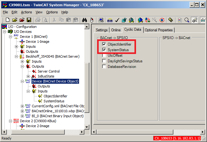
- The process data inputs: "_SystemStatus", "_ObjIdentifier" and outputs: "_ServerControl" of the device object have to be linked in the same way. This maps the status of the BACnet server and the local device object to the PLC.
- a) Create process data for the device object:
- b) Create link between PLC and I/O process data.
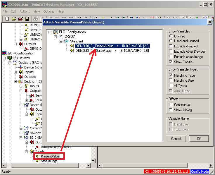
- All I/O signals of the PLC/BACnet function block "BI_0" now have to be linked with the actual BACnet object. The links are established in the same way as specified under item 9 ("_PresentValue" and "_StatusFlags"):
- To check the function without active PLC runtime, the configuration of the BACnet device and the hardware terminals can be tested in Free Run mode:
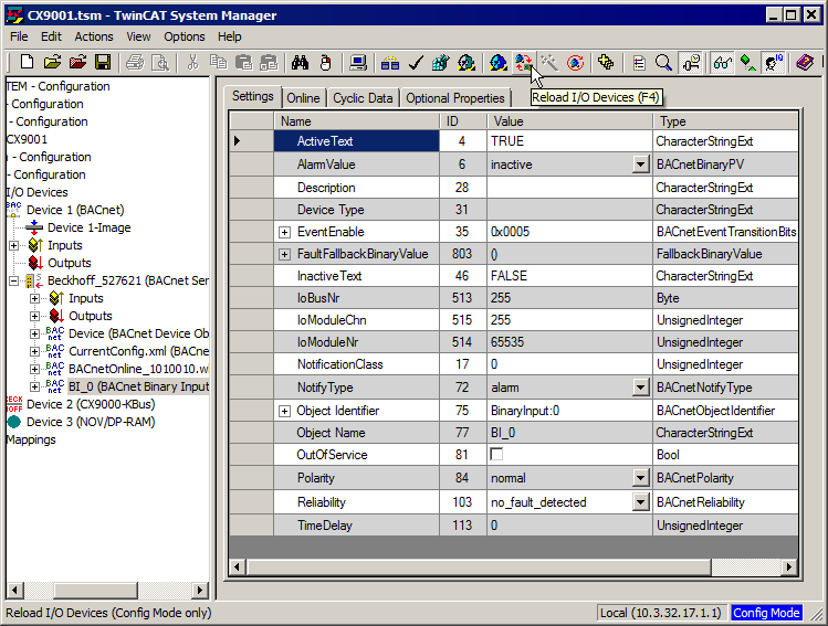
- a) Select "Reload I/O Devices (F4)" from the toolbar or press F4
- b) Select "Toggle Free Run State (Ctrl-F5)" from the toolbar or press CTRL+F5
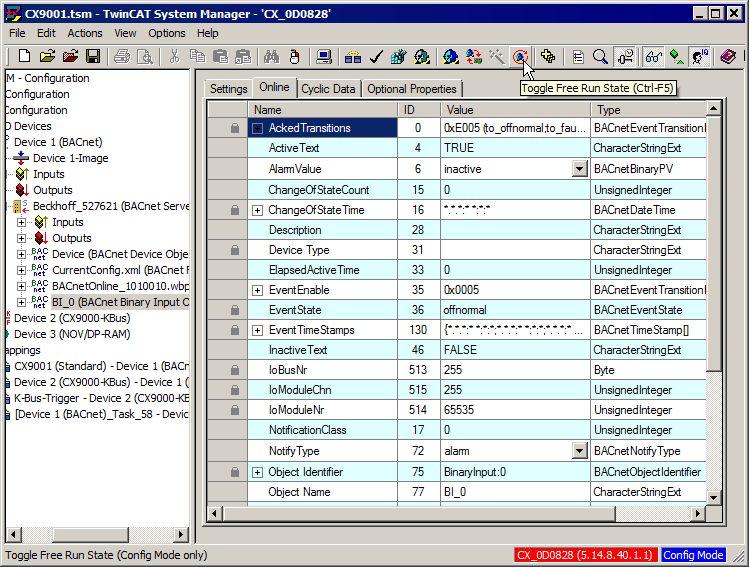
- c) The I/O bus of the target system should then switch to RUN. The state of the hardware input can now be monitored in the Online tab of the BACnet object "BI_0". The property Present_Value no. 85 represents the logical state of the hardware input. Using the context menu of "Online" tab, the Auto Update mode should be activated in advance (see chapter "BACnet objects and properties").
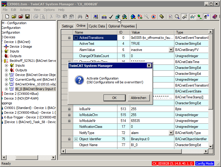
- After a successful test in "Free Run" mode the configuration has to be activated permanently. To this end activate the configuration as usual via the symbol "Activate Configuration" from the toolbar or by pressing CTRL+SHIFT+F4 (this loads the configuration into the target system):
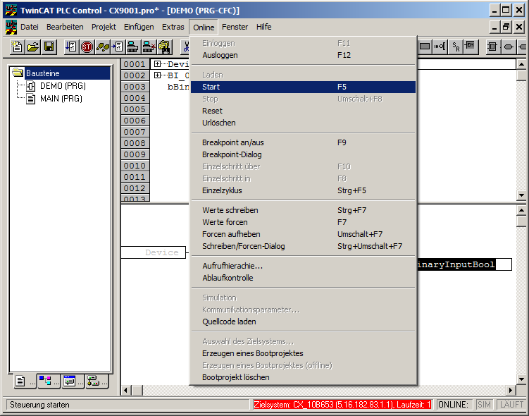
- This is followed by loading of the PLC runtime:
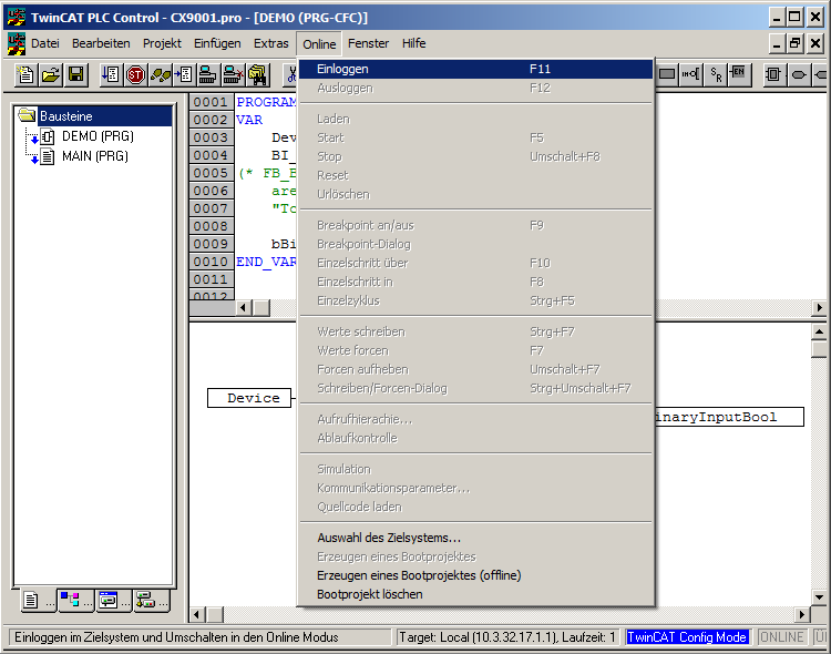
- and starting in RUN mode:
- The states of the BACnet object can be monitored via the Online view of the "DEMO" program. The state of signal Present_Value represents the logical state of the hardware input: