First steps
The steps necessary in order to create a solution with the TwinCAT BA Project Builder are shown in the following.
Creating a project
Call the dialog to create a new solution via the menu Solution -> New.
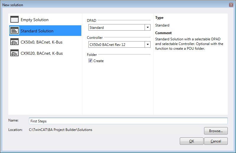
In this dialog you can specify the name of the solution and the path via which it should be saved. Furthermore, you must select the Data Point Addressing Description (DPAD) which will be used as the basis for the project engineering of the solution. The BA Project Builder offers the option of selecting an empty data point addressing description (DPAD) and defining the DPAD yourself.
Adding templates
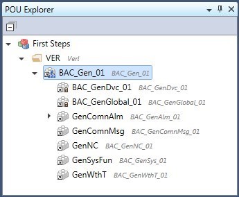
The POU Explorer defines the system structure on the software side. Folders in the POU Explorer define the individual levels (DPAD level). The possible identifiers (DPAD key) of a level are preset by the DPAD. The desired DPAD key can be selected via the Properties tool window.
Open the Templates tool window and drag the template BAC_Gen_01 onto the folder in the POU Explorer by drag & drop. This is a call template that inserts the basic PLC function blocks for the BACnet server into the PLC program. This call template is linked with further templates that are added automatically to the PLC program. All the POUs that have been added to the PLC project are displayed in the POU Explorer.
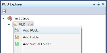
Alternatively, you can also add a POU via the context menu of the folder:
A double-click on a POU opens a dialog via which further parameters or BACnet properties can be edited.
Adding hardware
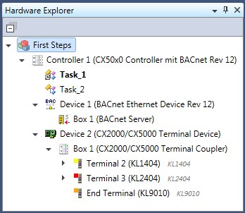
All controllers and their devices and terminals are assembled in the Hardware Explorer. When the new solution is created, a CX50x0 is automatically created with the necessary PLC tasks, BACnet server and I/O devices.
The terminal coupler Box 1 is located below Device 2. Now drag the terminals KL1404 and KL2404 out of the Terminals tool window into Box 1 by drag & drop. The Hardware Explorer should then look like this:
Here, too, you can alternatively add the terminals via the context menu.
Linking POUs with terminals.
If POUs have inputs and outputs they can be linked to the inputs and outputs of Bus Terminals.
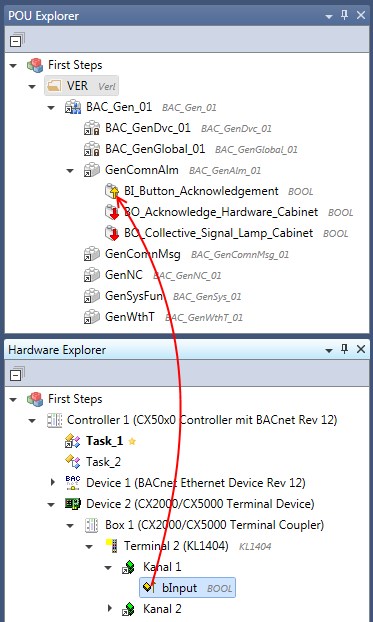
The links can be created by drag & drop or via the context menu.
Generating TwinCAT project files.
Once all POUs have been created and the parameters and BACnet properties have been set as desired and linked to the hardware, the TwinCAT project files can be generated. Call the menu Action -> Build Project Files.
Select the controller for which you want to generate the TwinCAT project files.
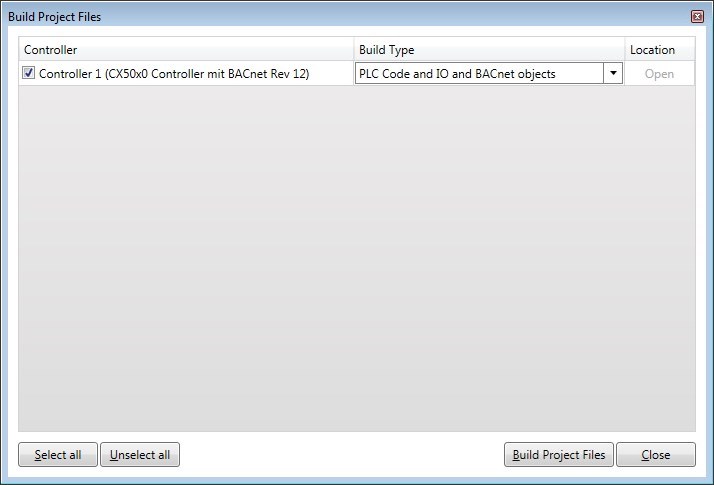
The column Build Type specifies which project files are created. This has a considerable influence on the time taken for the generation.
Requirements
PLC Code and IO and BACnet objects | The pro file for the TwinCAT PLC Control is generated and compiled. Furthermore, the tsm file is created for the TwinCAT System Manager with all I/O devices, BACnet objects and links. |
PLC Code and IO (without BACnet objects) | The pro file for the TwinCAT PLC Control is generated and compiled. Furthermore, the tsm file is created for the TwinCAT System Manager with all I/O devices and links. No BACnet objects are added. |
PLC Code (only pro file, no tpy file) | Only the pro file for the TwinCAT PLC Control is generated. The program is not compiled. |
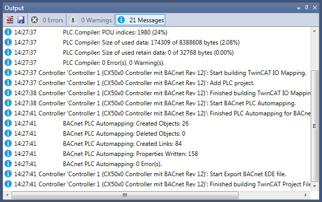
Various status messages are displayed in the Output tool window after the start of the generation.
These messages indicate whether all project files have been generated successfully or whether errors occurred.
A directory is created for each controller in the same folder in which the solution is saved. This directory has the same name as the controller in the BA Project Builder and has the subdirectory ~TwinCAT, where you will find the generated TwinCAT project files.