P_KL8524
IO template for parameterizing a KL8524: 4 x 2-channel digital output module. On PLC restart this template configures the terminal with the parameters entered in the Project Builder and then switches to process data mode. This template is based on the function block FB_KL8524.
Interface
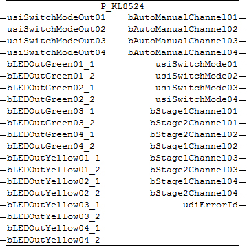
VAR_INPUT
usiSwitschModeOut01 .. usiSwitchModeOut04    : USINT;
bLEDOutGreen01_1 .. bLEDOutGreen04_2         : BOOL;
bLEDOutYellow01_1 .. bLEDOutYellow04_2       : BOOL;
usiSwitchModeOut01 .. usiSwitchModeOut04: Control of stages channel 1 to 4. Permissible values: "0", "1" and "2". All other inputs are interpreted as "0".
bLEDOutGreen01_1 .. bLEDOutGreen04_2: Control of the green LEDs channels 1 to 4, step 1 and 2, if switching of the LED from the PLC via the respective parameter bLEDModePLC01_1 to bLEDModePLC04_2 is enabled.
bLEDOutYellow01_1 .. bLEDOutYellow04_2: Control of the yellow LEDs channels 1 to 4, step 1 and 2, if switching of the LED from the PLC via the respective parameter bLEDModePLC01_1 to bLEDModePLC04_2 is enabled.
VAR_OUTPUT
bAutoManualChannel01 .. bAutoManualChannel04 : BOOL;
usiSwitchMode01 .. usiSwitchMode04           : USINT;
usiOnOffChannel01 .. usiOnOffChannel04       : USINT;
udiErrorId                                   : UDINT;
bAutoManualChannel01 .. bAutoManualChannel04: Status auto/manual selector switch channel 1 to 4: FALSE: Switch is set to "man", TRUE: Switch is set to "auto".
usiSwitchMode01 .. usiSwitchMode04: Numerical status (0, 1, 2) of the three-stage switch channels 1 to 4.
usiOnOffChannel01 .. usiOnOffChannel04: Active step channels 1 to 4: in manual mode (selector switch = man) that of the three-stage switch, in automatic mode (selector switch = auto) that of the respective input usiSwitchmodeOut01 to usiSwitchmodeOut04.
udiErrorId: contains the command-specific error code of the most recently executed command. See Error codes.
Parameter
bLEDModePLC01_1 .. bLEDModePLC04_2                  : BOOL;
iKBusOffModeChannel01 .. iKBusOffModeChannel04      : INT;
bOutModeChannel01 .. bOutModeChannel04              : BOOL;
usiSwitchDelayChannel01 .. usiSwitchDelayChannel04  : USINT;
bLEDModePLC01_1 .. bLEDModePLC04_2: If one of these parameters is set to TRUE, the standard function for the respective LED is deselected. That is, it is no longer influenced by the respective signal stage, but directly via the inputs bLEDOutGreen01_1 to bLEDOutGreen4_2 for the green colour scheme and bLEDOutYellow01 to bLEDOutYellow04_2 for the yellow colour scheme. It is possible to set both colours simultaneously. If the parameter is FALSE, the following applies: step not active = yellow, step active = green.
iKBusOffModeChannel01 .. iKBusOffModeChannel04: Selection of the behaviour on K-bus error: 0: no output is set, 1: step 1 is set, 2: step 2 is set. All other inputs are interpreted as "0".
bOutModeChannel01 .. bOutModeChannel04: Output mode channels 1 to 4: FALSE: output mode 1, TRUE: output mode 2, see guide FB_KL8524.
usiSwitchDelayChannel01 .. usiSwitchDelayChannel04: Input of the delay time for step 2 for the respective channel as multiple of 10 ms.
Development information
Entwicklungsumgebung | BACnet Revision | Target system | required supplement |
|---|---|---|---|
TwinCAT 2.11 R3/x64 from build 2254 | n/a | PC/CX | TS8040 | TwinCAT Building Automation from V1.1.0 |
Version history
Version number | Comments |
|---|---|
1.0.0.0 | First release |