User interface of the DC link
This chapter explains the user interface for the DC link.
DC link overview |
|
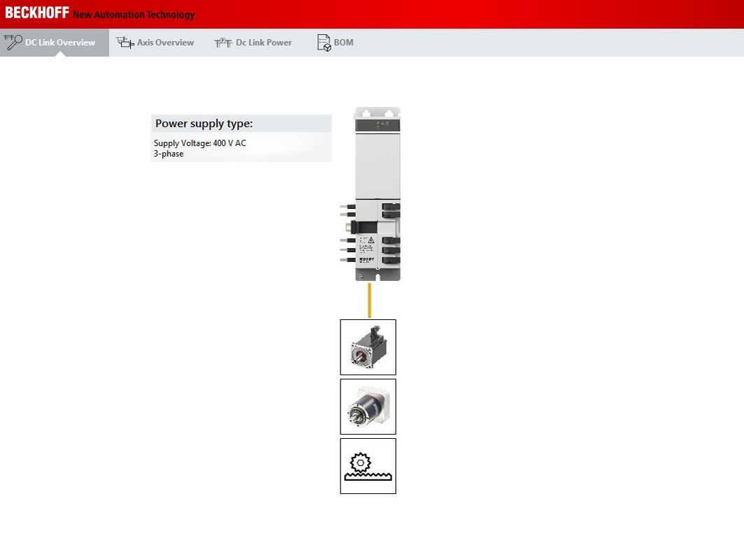
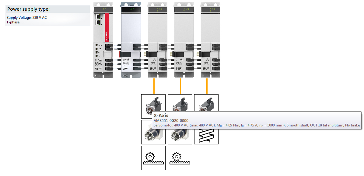
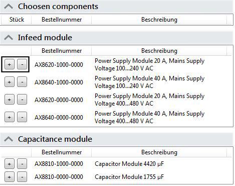
This menu item provides an overview of all the components created in your application, including a description of the supply. This overview
| For further information on the components of your DC link, move your cursor over the images under your supply or capacitor module. If the information does not appear immediately, move the cursor over the images again and leave it there for a while. |
|
|
Axis overview |
|
This overview shows all the available application values (e.g. position of your load case or speed of the used motors) in a coordinate system. The application values must first be selected in the pull-down menu. The graphs show the time dependency of all application values and the motors used in a common time base. | |
| |
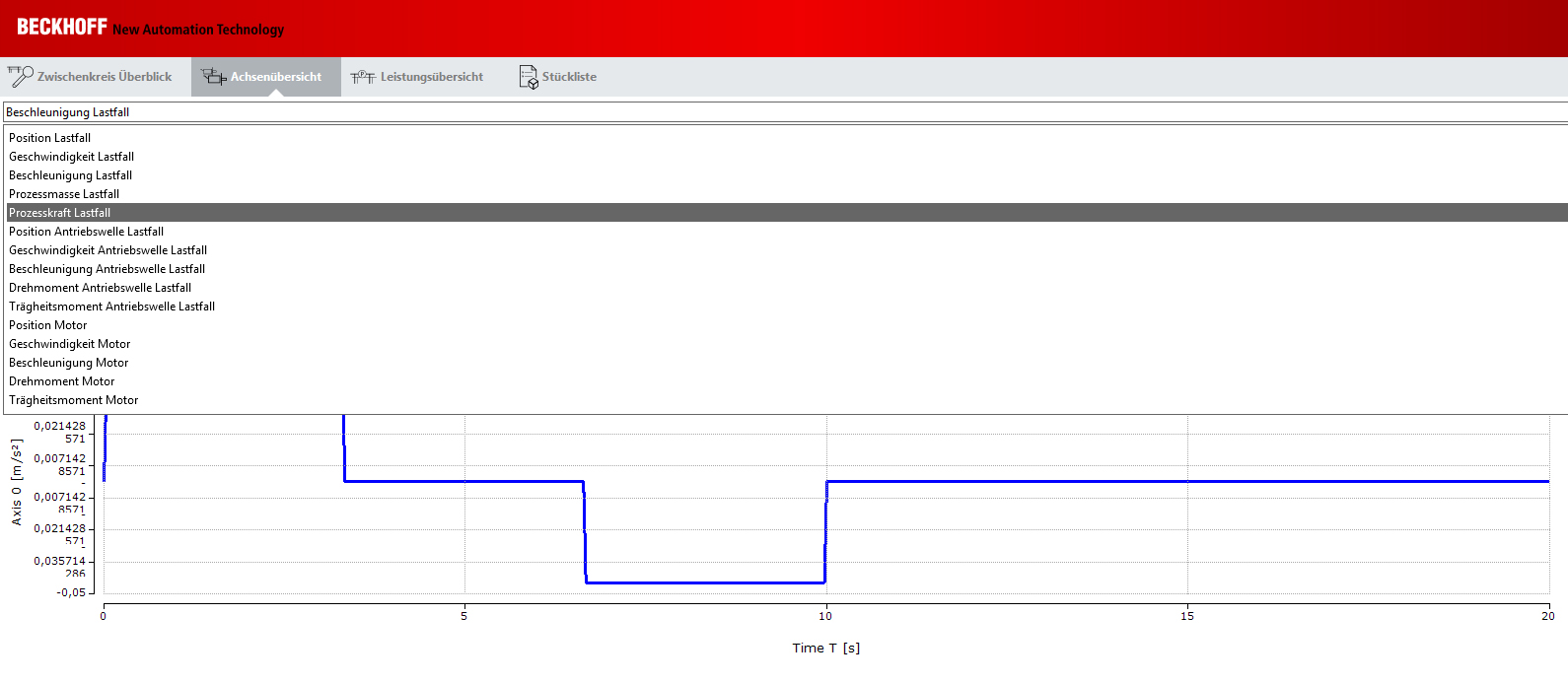
 | Selecting the application values: The TC3 Motion Designer offers a wide range of selectable application values. Please check the applicable application values, based on your processing steps, and depending on the application. |
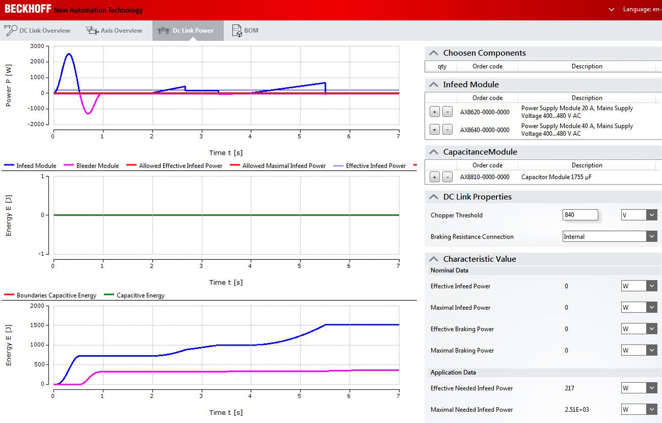
Performance overview | Operating elements for adding and removing |
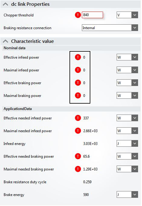
If your configuration is faulty (e.g. due to incorrectly dimensioned components), the TC3 Motion Designer reports an error. This is shown as a red circle with a white exclamation mark. To see a short description of the error, put the cursor Reference for the nominal and application values:
The characteristic values are calculated automatically. All components added to the DC link serve as basis.
| Use the + or - buttons to add components to your DC link or remove components (e.g. in the event of incorrect selection or configuration). When is it necessary to remove / add components?
Performance view These performance data are then graphically displayed in the performance view. The current values and application values are displayed. In this way, all settings can be visualized and double-checked.
|
| View of the added components: When you have dimensioned your DC link, |