Load cases
This section provides basic information about the load cases available for selection in TC3 Motion Designer. The different mechanical systems used in a machine require various data for calculating torques, speeds and loads. TC3 Motion Designer offers different load cases for visualizing this information.
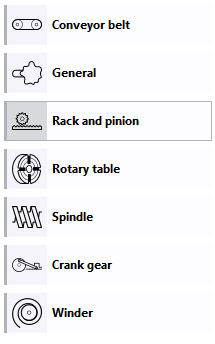
Overview of load cases |
|
| TC3 Motion Designer enables calculation of 7 different load cases. Select the load case that matches the requirements for your application. |
|
 You are currently on the first tab of the progress bar. The activated tabs are highlighted in grey and show the icon for the respective configuration step. A more detailed description can be found in chapter: “
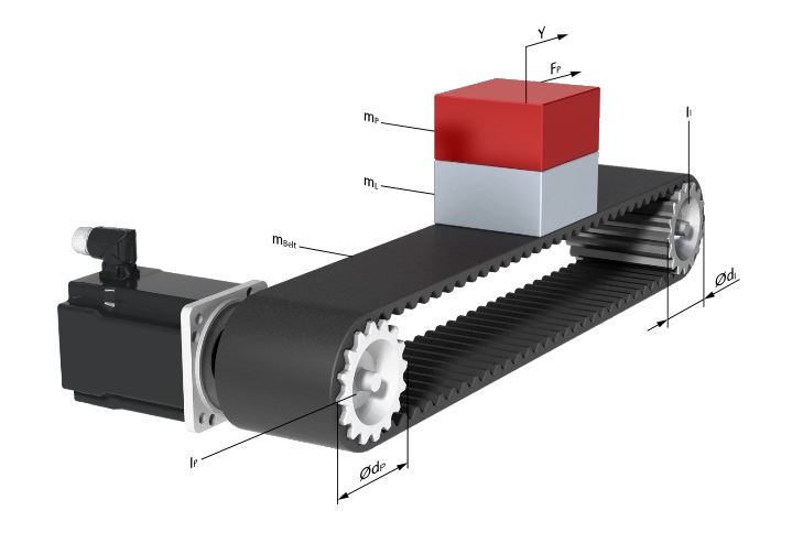
Load case 1: Conveyor belt |
| Load case 2: General |
The conveyor belt load case enables calculation of a range of drive configurations, from simple toothed belt drives to complex belt drives with tension roller and weight compensation. This load case has low to medium Usually a gear unit is used. |
| This load case covers all cases that are not specified in more detail. The only parameter to be specified is the driven mass inertia. The settings areas for the general load case are the same as for the more detailed specifications and have no special characteristics.
|
|
|
|
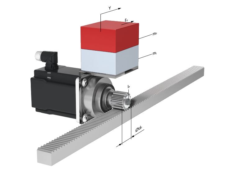
Load case 3: Pinion rack |
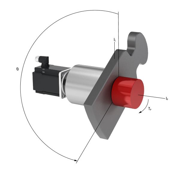
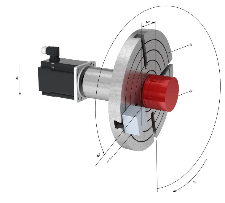
| Load case 4: Rotary indexing table |
This load case relates to exacting applications with high precision requirements. Usually a high-quality gear unit with reinforced bearings is used, in order to be able to cope with high radial forces. |
| The rotary indexing table is also referred to as rotary table or rotary switching table. The advantage of servo drives is flexible and easily adaptable graduation. A-centric masses are also taken into account. |
|
|
|
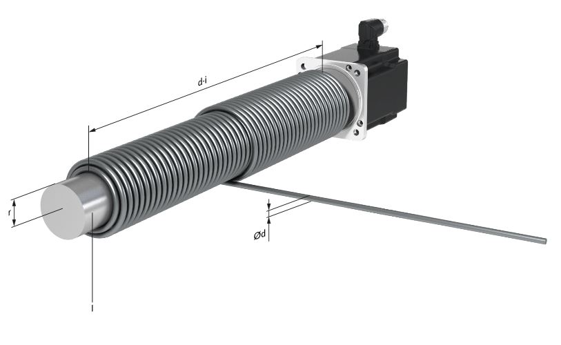
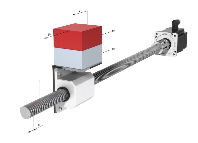
Load case 5: Spindle drive |
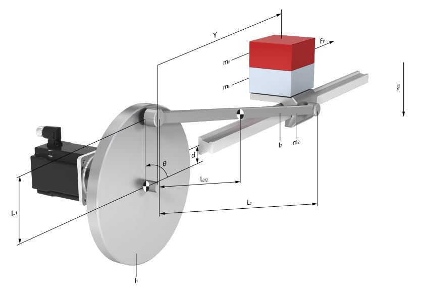
| Load case 6: Crank drive |
This load case is used for medium to high-precision linear movements. The motor is usually coupled directly to the spindle. |
| This load case is characterized by complex mechanics, which directly transform the rotary movements of the motor into a linear motion. |
|
|
|
|
|
Load case 7: winder |
|
| This load case enables calculation of winding processes with single-layer media (e.g. paper rolls) or with several windings per layer (e.g. cable winch). |