Online
The Online tab is the main dialog for online axis operation. Here the enable can be set and after this the corresponding axis can be moved manually. In addition, the most important axis states are displayed when the configuration is active.
| |
Risk of injury due to movement of axes! The commissioning results in a movement of axes.
|

| |
Incorrect axis position during initial commissioning Without referencing / calibrating the axis position, the displayed axis position may deviate from the actual axis position.
|
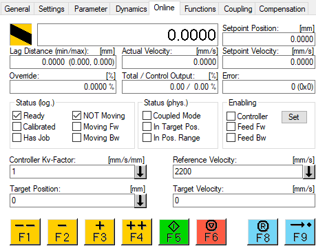
The dialog is divided into the display of the most important axis states, the setting of the axis enable, input fields as well as function keys for controller settings and travel commands. The units of the values depend on the set "Base" unit.
Display
The actual position of the axis is determined from the feedback of the encoder system and displayed in the large unlabeled field.
Setpoint Position | The target position is specified by the NC during a movement. |
Lag Distance | The lag error is the difference between the nominal and actual position. |
Actual Velocity | The actual velocity of the axis is determined by deriving the actual position. |
Setpoint Velocity | The target velocity is calculated by the NC during a movement. |
Override | The override set by the user (0..100%) is displayed here. |
Total/Control Output | Total output of the NC axis to the drive in % and position control portion of the output in %. |
Error | Axle error code. An axis error can be deleted with the reset key. |
Set enables
Via the button Set the controller enable, the feed enables and the override of the axis can be set.
Input fields for position controller setting
If the NC axis is operated in velocity mode (CSV), the position is controlled by the NC. At this point the two most important parameters, the gain factor Kv and the reference velocity, can be set. Further setting options can be found in the parameters of the axis.
Input fields for travel commands
Target Position: Target position for a subsequent travel command (F5)
Target Velocity: Velocity of a subsequent travel command (F5)
Function button
Button | Key | Description |
|---|---|---|
| F1 | Reverse travel with Manual Velocity (Fast) |
| F2 | Reverse travel with "Manual Velocity (Slow)" |
| F3 | Forward travel with "Manual Velocity (Slow)" |
| F4 | Forward travel with "Manual Velocity (Fast)" |
| F5 | Start, with the values set in the input fields and the set dynamics. |
| F6 | Stop |
|
|
|
| F8 | Reset |
| F9 | Calibrate with the values set in the "Global" menu. |


