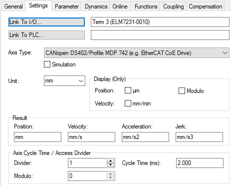
Settings
In the Settings tab, essential settings like linking the NC axis with hardware and PLC as well as type and unit can be executed.
Setting | Description | |
|---|---|---|
Link To I/O… | The Link button opens a dialog for linking the NC axis with the drive hardware under I/O. | |
Link To PLC… | The Link button opens a dialog for linking the NC axis with the PLC instance of the axis. | |
Axis Type | Type of connected drive hardware and protocol used. | |
Simulation | From TwinCAT 3.1 Build 4026 Enables the axis to be set to simulation mode. If simulation mode is active, the link to the I/O is ignored and a simulation drive and encoder are used instead of the configured axis type. If simulation mode is active, the axis is marked with a light blue symbol in the project tree | |
Unit | Physical unit of the position of the axis. The unit can be chosen arbitrarily and edited in the Unit input field. It should be noted that the scaling factor of the axis must be set accordingly (see Encoder parameters). Standard: Millimeter (mm) | |
Display (only) | Adjustments to the display in the online axis dialog. These settings do not affect data in the process image. | |
| Position | Changes the position display by one thousand place value (mm/µm) |
| Velocity | Display of velocity in mm/min instead of mm/s. The default time reference in NC and PLC remains the second regardless of the display setting. |
| Modulo | Display of the modulo position instead of the absolute position. |
Result |
| |
| Position | Position |
| Velocity | Velocity |
| Acceleration | Acceleration |
| Jerk | Jerk |
Axis Cycle Time / Access Divider |
| |
| Divider | The axis is executed in every nth cycle of the NC-SAF task with the cycle time divider. The divider can be set to a value greater than 1 to reduce the system load for low-priority axes. |
| Modulo | With a cycle time divider greater than 1, the modulo value determines in which NC-SAF cycle the axis is processed. Axes with the same modulo are processed in the same cycle. For even distribution of the system load, the axes should be distributed to different modulo values. |
| Cycle Time (ms) | Axis cycle time |
 .
.