Your first TwinCAT 3 PLC project
Contents of your first project
In this tutorial, you will program a simple refrigerator control.
- As with a conventional refrigerator, the set temperature is set by the user via a control knob.
- The refrigerator detects the actual temperature via a sensor. If this is too high, the refrigerator starts the compressor with an adjustable delay.
- The compressor cools until the set temperature minus a hysteresis of 1 degree is reached. The hysteresis is intended to prevent the actual temperature from oscillating too much around the set temperature, and to prevent the compressor from continuously switching on and off.
- When the door is open, a lamp lights up inside the refrigerator.
- If the door is open for too long, a timed acoustic signal will sound.
- If the compressor does not reach the set temperature for an extended period of time despite the motor's activity, the beeper emits a continuous acoustic signal.
Project planning:
The cooling activity is controlled in the main program of the PLC project, the signal management take place in another program block. The required standard function blocks are available in the Tc2_Standard library. Since no real temperature sensors and no real actuators are connected in this example project, you will also write a program for simulating the rise and fall in temperature. This allows you to monitor the operation of the refrigerator control unit in online mode. You define variables that are to be used by all function blocks in a global variable list.
Creating the PLC project
- 1. In the File menu, select New > Project to create a new TwinCAT project file.
- A new Solution with the TwinCAT project tree opens in the Solution Explorer.
- 2. In the Solution Explorer select the PLC node and the command Add New Item, in order to add a PLC project to the TwinCAT project.
- The dialog Add New Item – TwinCAT <project name> opens.
- 3. In the category Plc Templates select the Standard PLC project template.
- 4. Enter a name and storage location for the project and click the Add button.
- The selected template automatically creates a MAIN program, which is called by a task. "Structured Text (ST)" is automatically selected as the programming language.
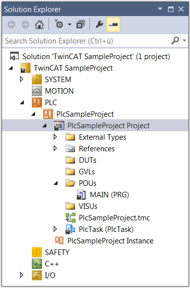
The Library Manager with some important default libraries is automatically selected under References. The Tc2_Standard library contains all the functions and function blocks described by the IEC 61131-3 standard.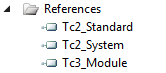
Declaring global variables
First, declare the variables that you want to use throughout the PLC project. To do this, you create a global variable list:
- 1. Select the subfolder GVLs in the PLC project tree.
- 2. In the context menu select the command Add > Global Variable List.
- 3. Change the automatically entered name "GVL" to "GVL_Var".
- 4. Confirm with Open.
- The object “GVL_Var” (
 ) appears in the PLC project tree in the subfolder GVLs. The GVL editor opens.
 - When the textual view appears, the keywords VAR_GLOBAL and END_VAR are already included.
- 5. Activate the tabular view for the example by clicking on the
 button in the right sidebar of the editor.
 - An empty row appears. The cursor is located in the column Name.
- 6. Enter “fTempActual” in the Name field.
- At the same time, the scope VAR_GLOBAL and the data type BOOL are automatically entered in the row.
- 7. Double-click the field in the Data type column.
- The field is now editable, and the button
 appears.
 - 8. Click the button and select Input Assistant.
- The Input Assistant dialog opens.
- 9. Select the data type REAL and click OK.
- 10. Enter a numerical value in the Initialization column, for example “8.0”.
- Declare the following variables in the same way:
Name | Data type | Initialization | Comment |
|---|---|---|---|
fTempActual | REAL | 1.0 | Actual temperature |
fTempSet | REAL | 8.0 | Set temperature |
bDoorOpen | BOOL | FALSE | Door status |
tImAlarmThreshold | TIME | T#30s | Compressor running time after which an alarm sounds. |
tDoorOpenThreshold | TIME | T#10s | Time from door opening after which an alarm sounds. |
xCompressor | BOOL | FALSE | Control signal |
xSignal | BOOL | FALSE | Control signal |
xLamp | BOOL | FALSE | Status message |
Creating the main program for cooling control in the CFC editor
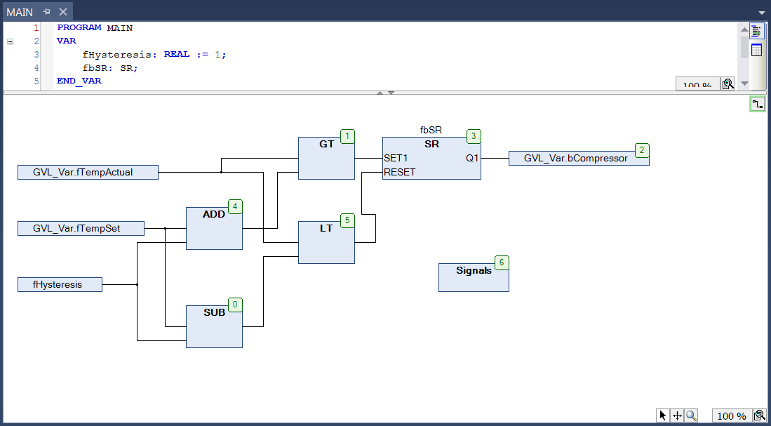
In the MAIN program block created by default, you describe the main function of the PLC program: The compressor becomes active and cools when the actual temperature is higher than the set temperature plus a hysteresis. The compressor is switched off when as the actual temperature is lower than the set temperature minus the hysteresis.
Perform the following steps to describe this functionality in the implementation language "Continuous Function Chart (CFC)":
- Since the automatically created MAIN program block is created by default in the implementation language "Structured Text (ST)", you must first delete this program. With the context menu command Add > POU... you create a new MAIN program in the implementation language "Continuous Function Chart (CFC)".
- 1. Then double-click on the MAIN program in the PLC project tree (subfolder POUs).
- The CFC Editor opens with the MAIN tab. The Declaration editor in textual or tabular representation is displayed above the graphical editor area. On the right is the Toolbox view. If the toolbox does not appear, you can use the command Toolbox in the View menu to place it on the desktop.
- 2. In the Toolbox view, click the Input element and drag it with the mouse to a position in the CFC Editor.
- The nameless input ??? has been inserted.
- 3. In the CFC Editor, click the input ??? and open the Input Assistant by clicking
 .
. - 4. Select the variable
fTempActualfrom the category Variables at Project > GVLs. - 5. Confirm the dialog with OK to reference the global variable
fTempActual. - 6. As in step 3, create a further input with the name of the global variable
rTempSet. - 7. Create another input.
- 8. Click ??? and replace it with the name
fHysteresis. - Since this is not the name of an already known variable, the Auto Declare dialog appears. The name is already included in the dialog.
- 9. Complete the fields in the Auto Declare dialog with the data type REAL and the initialization value "1".
- 10. Click the OK button.
- The variable
fHysteresisappears in the declaration editor. - 11. Now add an addition function block: In the Toolbox view, click the Function block element and drag it with the mouse to a position in the CFC Editor.
- The function block appears in the CFC Editor.
- 12. Replace ??? with ADD.
- The ADD (Addition) function block adds all inputs that are connected to it.
- 13. Connect the input GVL_Var.fTempSet with the ADD function block: To do this, click on the output connector of the input and drag it to the upper input of the ADD function block.
- 14. Connect the
fHysteresisinput to the lower input of the ADD function block in the same way. - The two inputs
fHysteresisandfTempSetare now added by ADD. - 15. If you want to move an element in the editor, click on a free space in the element or on the frame so that the element is selected (red frame, shaded red).
- 16. Keep the mouse button pressed and drag the element to the desired position.
- 17. Create another function block to the right of the ADD function block.
- It is intended to compare "GVL_Var.fTempActual" with the sum of "GVL_Var.fTempSet" and fHysteresis.
- 18. Assign the function GT (Greater Than) to the function block.
- The GT function block works as follows:
IF (oberer Eingang > unterer Eingang) THEN Ausgang := TRUE; - 19. Connect the input "GVL_Var.fTempActual" with the upper input of the GT function block.
- 20. Connect the output of the ADD function block with the lower input of the GT function block.
- 21. Now create a function block to the right of the GT function block that starts or stops the cooling compressor depending on the input condition (Set - Reset).
- 22. Enter the name "SR" in the ??? field.
- 23. Close the open input field above the function block (SR_0) with the Enter key.
- The Auto Declare dialog appears.
- 24. Declare the variable with the name "fbSR" and the data type SR.
- 25. Click the OK button.
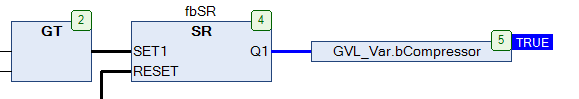
- The SR function block, which is also defined in the library Tc2_Standard, determines the THEN at the output of the GT function block. The inputs SET1 and RESET appear.
- 26. Connect the output connection on the right of the GT function block to the SET1 input of the fbSR function block.
- SR can reset a Boolean variable from FALSE to TRUE. If the condition applies at input SET1, the Boolean variable is set to TRUE. If the condition applies to RESET, the variable is reset. In our example, the Boolean (global) variable is "GVL_Var.bCompressor".
- 27. Create an Output element and assign the global variable "GVL_Var.bCompressor" to it. Draw a connecting line between "GVL_Var.bCompressor" and the output connection from Q1 to SR.
Now enter the condition under which the compressor should switch off again, i.e. under which the RESET input of the SR function block receives a TRUE signal. To do this, formulate the opposite condition as described above. Use the function block SUB (Subtract) and LT (Less Than) for this purpose.
The following CFC plan is created:
Creating a program block for signal management in the Ladder Diagram editor
Now implement the signal management for the alarm buzzer and for switching the lamp on and off in a further program block. The implementation language "Ladder Diagram (LD)" is suitable for this purpose.
Use separate networks for the following signals:
- A continuous acoustic signal sounds if the compressor runs too long because the temperature is too high.
- A pulsed signal sounds if the door is open too long.
- The light is on as long as the door is open.
- 1. In the PLC project tree (subfolder POUs) create a POU object of type Program with the implementation language "Ladder Diagram (LD)".
- 2. Name the POU object "Signals".
- "Signals" appears in the PLC project tree below MAIN. The Ladder Diagram editor opens with the Signals tab. The declaration editor appears in the upper part of the screen, the Toolbox view on the right. The LD contains an empty network.
- 3. In the network, you program that an acoustic signal sounds if the cooling compressor runs for too long without reaching the set temperature. To do this, insert a TON timer function block.
- It switches a Boolean TRUE signal to TRUE after a specified time.
- 4. Select a TON in the Toolbox view under Function blocks and drag it into the empty network to the Start here rectangle, which appears.
- 5. Release the mouse button when the field turns green.
- The function block appears as rectangle with inputs and outputs and is automatically assigned the instance name TON_0. The line editor is open and the cursor is blinking.
- 6. Confirm the instance name with Enter key.
- The Auto Declare dialog opens.
- 7. Declare the variable with the name "fbTimer1" and the data type TON.
- 8. Click the OK button.
- 9. To program that the function block is activated as soon as the cooling compressor starts running, name the contact at the upper input of the function block "GVL_Var.bCompressor".
- You have already defined this Boolean variable in the global variable list "GVL_Var".
- 10. Insert the signal you want to activate: To do this, drag a Coil from the Toolbox view, category Ladder Diagram elements to output Q of the TON function block. Name the coil "GVL_Var.bSignal".
- 11. Add the variable "GVL_Var.tImAlarmThreshold" to the PT input of "fbTimer1" to define the time from activation of the TON device after which the signal should sound. To do this, click on the rectangle with a border to the right of the input connection.
- 12. Enter the variable name.
- 13. Click the TON function block and in the context menu select the command Remove unused FB call parameters.
- The unused output ET was removed.
- 14. In the second LD network, you program that the signal should sound intermittently when the door is opened too long.
- 15. First, create a new POU object of type Function Block in the implementation language "Function Block Diagram (FBD)" in the PLC project tree, subfolder POUs.
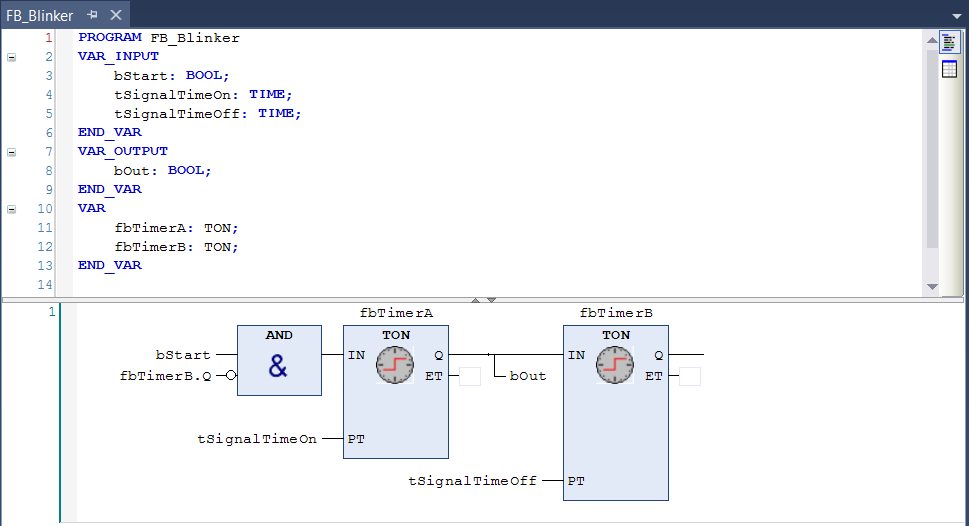
- 16. Name it "FB_Blinker".
- The function block FB_Blinker appears in the PLC project tree above MAIN. The FBD editor opens with the FB_Blinker tab. The declaration editor appears in the upper part of the screen, the Toolbox view on the right. The FBD contains an empty network.
- The flasher is to be realized by an AND operator and two TON function blocks.
- 17. Select a function block in the Toolbox view under General and drag it into the empty network to the Start here rectangle, which appears.
- 18. Release the mouse button when the field turns green.
- The function block appears as a rectangle with inputs and outputs.
- 19. Click ??? within the function block and enter the keyword AND in the field, which is now editable.
- 20. Confirm with Enter key.
- Since it is a function, no instantiation is required.
- 21. Select a TON function block in the Toolbox view under Function blocks and drag it into the network to the output of the AND function block.
- 22. Release the mouse button when the field turns green.
- The function block appears as rectangle with inputs and outputs and is automatically assigned the instance name TON_0.
- 23. Close the open input field above the function block (TON_0) with the Enter key.
- The Auto Declare dialog opens.
- 24. Declare the variable with the name “fbTimerA” and the data type TON.
- 25. Click the OK button.
- 26. Select a further TON function block in the Toolbox view under Function blocks and drag it into the network to the output of the TON function block "fbTimerA".
- 27. Release the mouse button when the field turns green.
- The function block appears as rectangle with inputs and outputs and is automatically assigned the instance name "TON_0".
- 28. Close the open input field above the function block (TON_0) with the Enter key.
- The Auto Declare dialog opens.
- 29. Declare the variable with the name “fbTimerB” and the data type TON. Click the OK button.
- The first input of the AND function block is to be connected to a Boolean variable "bStart".
- 30. Click ??? and enter the variable name.
- 31. Confirm with Enter key.
- The Auto Declare dialog opens. The name and the data type are recognized automatically.
- 32. Select the entry VAR_INPUT as Scope.
- 33. Confirm the dialog with OK.
- The second input of the AND function block is to be connected with the output Q of the second TON function block "fbTimerB".
- 34. Click ??? and open the Input Assistant via .
- 35. In the category Variables select the function block "fbTimerB" and the output Q.
- 36. Confirm the dialog with OK.
- The variable "fbTimerB.Q" is added at the second input.
- 37. Select the second input and open the context menu with a right-click.
- 38. Select the command Negation to negate the input.
- A circle appears at the corresponding input.
- 39. Set the time until output Q is set via the PT inputs of the TON function blocks.
- 40. Declare the input variables "tSignalTimeOn" and "tSignalTimeoff" for the TON function blocks "fbTimerA" and "fbTimerB" via the Auto Declare dialog.
- 41. Select the entry VAR_INPUT as Scope.
- The generated clock pulse is to be output at output Q of the TON function block "fbTimerA".
- 42. To do this, select an assignment in the Toolbox view under General and drag it into the network to the output of the TON function block "fbTimerA".
- 43. Release the mouse button when the field turns green.
- The assignment is added between the function blocks "fbTimerA" and "fbTimerB".
- 44. Click ??? and enter the variable name "bOut".
- 45. Confirm with Enter key.
- The Auto Declare dialog opens.
- 46. Select the Scope VAR_OUTPUT and the data type BOOL.
- 47. Confirm the dialog.
- 48. Finally, remove the ??? at the unused inputs and outputs of the function blocks.
- The completed function block FB_Blinker can now be instantiated and called.
- 49. Open the program "Signals" in the FBD/LD/IL editor.
- 50. Click below the first network in the editor window.
- 51. In the context menu, select the command Insert network.
- An empty network with number 2 appears.
- 52. As in the first network, implement a TON function block for time-controlled activation of the signal, this time triggered by the global variable "GVL_Var.bDoorOpen" at input IN.
- 53. Add the global variable "GVL_Var.tImDoorOpenThreshold" at the input PT.
- 54. In addition, add the function block FB_Blinker to output Q of the TON function block in this network.
- The function block FB_Blinker clocks the signal forwarding Q and therefore "GVL_Var.bSignal".
- 55. To do this, drag a Contact element from the Toolbox view to the OUT output of the function block.
- 56. Assign the variable "fbTimer2.Q" to the contact.
- 57. Insert an element Coil after the contact and assign the global variable "GVL_Var.bSignal" to it.
- 58. Assign the value T#1s to the two input variables "tSignalTimeOn" and "tSignalTimeOff" of function block FB_Blinker.
- The cycle time is then 1 second for TRUE and 1 second for FALSE.
- 59. Click on the TON function block.
- 60. Select the command Remove unused FB call parameters in the context menu.
- The unused output ET was removed.
- In the third network of the LD, program the lamp to light up while the door is open.
- 61. To do this, add another network and at the left a contact "GVL_Var.bDoorOpen", which leads directly to an inserted coil "GVL_Var.bLamp".
- TwinCAT processes the networks of an LD in succession.
- 62. To ensure that only network 1 or only network 2 is executed, add a jump to network 3 at the end of network 1.
- 63. Select network 3 by clicking into the network or into the field with the network number.
- 64. From the context menu select the command Insert label.
- 65. Replace the text Label: of the label in the upper left section of the network with "DoorIsOpen".
- 66. Select network 1.
- 67. Drag the Jump element into network from the Toolbox view, General category.
- 68. Position it on the Output rectangle that appears, or at Insert jump here.
- The jump element appears. The jump destination is still shown as ???.
- 69. Selecting ??? and click .
- 70. Select “DoorIsOpen” from the possible label identifiers.
- 71. Confirm with OK.
- The label to network 3 is implemented.
 | If you want to read the help for the function block, mark the complete name of the function block with the cursor and press [F1]. |
| When you start entering a variable name at the input position, you will always automatically receive a list of all variables whose names begin with the characters entered and which can be used at this point. This feature is a default setting in the TwinCAT options for Smart Coding. |
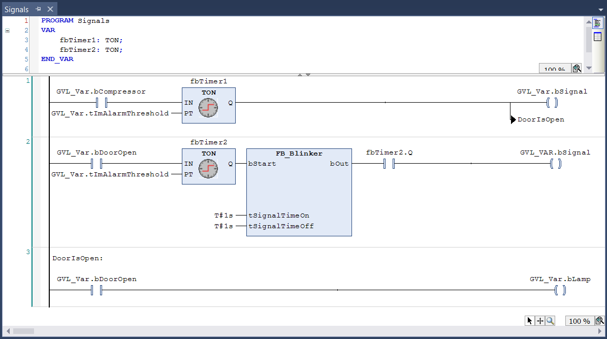
- The LD program now looks as follows:
Calling the “Signals” program in the main program
In our sample program, the MAIN program should call the “Signals” program for signal processing.
- 1. In the PLC project tree double-click on the MAIN program.
- The MAIN program opens in the editor.
- 2. Drag a Box element from the Toolbox view into the editor of MAIN.
- 3. Use the Input Assistant to add the "Signals" program call to this function block from the Module Calls category.
Creating an ST program block for a simulation
Since this sample project is not linked to real sensors and actuators, write a program for simulating the rise and fall in temperature. This allows you to monitor the operation of the refrigerator control unit in online mode.
Use "Structured Text (ST)" to create the simulation program.
The program increases the temperature until the MAIN program detects that the set temperature has been exceeded and activates the cooling compressor. The simulation program then lowers the temperature again until the main program deactivates the compressor.
- 1. Add a POU function block called "Simulation" of type Program and written in the implementation language "Structured Text (ST)" to the PLC project tree.
- 2. Implement the following in the ST editor:
PROGRAM Simulation
VAR
    fbT1                 : TON;             //The temperature is decreased on a time delay, when the compressor has been activated
    tCooling             : TIME := T#500MS;
    bReduceTemp          : BOOL;            //Signal for dereasing the temperature
    fbT2                 : TON;             //The temperature is increased on a time delay, when the compressor has been activated
    tEnvironment         : TIME := T#2S;    //Delay time when the door is closed
    tEnvironmentDoorOpen : TIME := T#1s;    //Delay time when the door is open
    bRaiseTemp           : BOOL;            //Signal for increasing the temperature
    tImTemp              : TIME;            //Delay time
    nCounter             : INT;
END_VAR

// After the compressor has been activated due to fTempActual being too high, the temperature decreases.
// The temperature is decremented by 0.1°C per cycle after a delay of P_Cooling
IF GVL_VAR.bCompressor THEN
    fbT1(IN:= GVL_Var.bCompressor, PT:= tCooling, Q=>bReduceTemp);
    IF bReduceTemp THEN
        GVL_Var.fTempActual := GVL_Var.fTempActual-0.1;
        fbT1(IN:=FALSE);
    END_IF
END_IF

//If the door is open, the warming will occur faster; SEL selects tEnvironmentDoorOpen
tImTemp:=SEL(GVL_Var.bDoorOpen, tEnvironment, tEnvironmentDoorOpen);

//If the compressor is not in operation, then the cooling chamber will become warmer.
//The  temperature is incremented by 0.1°C per cycle after a delay of tImTemp
fbT2(IN:= TRUE, PT:= tImTemp, Q=>bRaiseTemp);
IF bRaiseTemp THEN
    GVL_Var.fTempActual := GVL_Var.fTempActual + 0.1;
    fbT2(IN:=FALSE);
END_IF

nCounter := nCounter+1; // No function, just for demonstration purposes.
| Visualization For convenient operation and monitoring of the entire control program, a visualization can be used that displays the refrigerator and shows the operation of the simulation program. In TwinCAT, you can also program a visualization in the PLC area. When the project is started on the controller, the visualization starts without you having to make an entry. Depending on the programming, you can trigger opening and closing of the door by clicking an on/off switch, for example, or by adjusting the temperature preselection using the needle of a control knob. The process of creating a visualization is not described here. |
Defining the programs to be executed in the task configuration
The preset task configuration contains the call for the MAIN program. For our sample project you have to add the call for the program "Simulation".
- 1. In the PLC project tree, drag the "Simulation" entry to the task reference (PlcTask).
- The "Simulation" program is added to the task configuration.
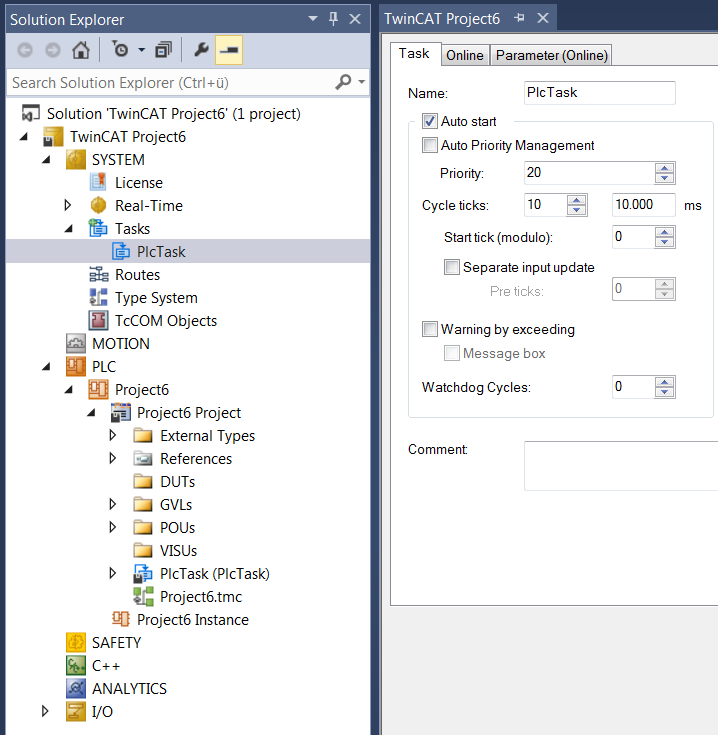
- 2. To view the task configuration, double-click the PlcTask entry in the PLC project tree.
- In the Solution Explorer the referenced task (PlcTask) is enabled under SYSTEM > Tasks.
- 3. Double-click the task to open the task's configuration in an editor.
- In the PLC project tree at PlcTask you see the POUs that are called by the task: MAIN (entered by default) and Simulation. The editor of the PlcTask node in the SYSTEM area shows the corresponding cycle time for the referenced PlcTask. In this sample, the interval is 10 milliseconds. In online mode, the task will process the two function blocks once per cycle.
Defining the active PLC project
A TwinCAT controller can run multiple PLC projects. The first entry in the Active PLC Project drop-down list in the TwinCAT PLC Toolbar Options shows the currently active PLC project. If several PLC projects are present, you can select a PLC project via the drop-down list.
Checking the PLC project for errors
While entering code, TwinCAT immediately alerts you to syntax errors by means of a squiggly red line.
- 1. To get a syntax check over the whole PLC project, select the PLC project object "<PLC project name> Project".
- 2. Choose the command Check all objects from the context menu or from the Build menu.
- The results of the check are displayed in the Error List view.
- 3. If necessary, open the Error List view with the command Error List from the View menu.
- 4. You can then double-click the message to jump to the corresponding code position.
The command Check all objects can be used to check and compile all function blocks in the PLC node. An error is generated if the compilation reveals function blocks in the tree that are uncompilable, for example because they may only have been included for testing purposes. It is therefore advisable to run the command Check all objects, particularly for checking library function blocks.
The commands Build or Rebuild can be used to limit checking and compiling to function blocks that are actually used in the PLC project.
Further checks of the PLC project are performed when it is loaded onto the controller.
Only error-free PLC projects can be loaded onto the controller.
Compiling the PLC module
The commands Build or Rebuild can be used to compile your code used in the PLC project and check for syntactic accuracy.
Choose Target System
Now select the target device for your control program from the Choose Target System drop-down list in the TwinCAT XAE Base Toolbar Options:
- Select <Local> to load the control code directly into the local runtime of your programming device. (Select this options for the present sample.)
- If you want to select another target device, select Choose Target System from the drop-down list. Then select a preconfigured target device or browse the network for a target device, configure it and then select it.
Activation of the configuration
- 1. Click
 in the TwinCAT XAE Base Toolbar Options.
 - A dialog appears asking whether you want to activate the configuration.
- 2. Click on OK.
- A dialog appears asking whether TwinCAT should be restarted in Run mode.
- 3. Click on OK.
- The configuration is activated, and TwinCAT is set to Run mode. In the taskbar shows the current status:
 . Activation also transfers the PLC project to the controller.
Loading the PLC project onto the PLC
- The PLC project was compiled without errors. See step Checking the PLC program for errors,
- 1. Select the Login command in the PLC menu or click on
 in the TwinCAT PLC Toolbar Options.
 - A dialog box appears asking whether the application should be created and loaded.
- 2. Click Yes.
- The PLC project is loaded onto the controller. The engineering environment is now in online mode. The PLC modules are not yet in Run mode. In the Solution Explorer the following symbol appears before the PLC project object:
 . During the loading process, the Error List view displays information about the generated code size, the size of the global data and the resulting memory requirements on the controller.
Starting the program
If you have followed the entire tutorial up to this point, you can now use the PLC project on the PLC device.
- 1. Select the Start command in the PLC menu or click on
 in the TwinCAT PLC Toolbar Options ([F5]).
- The program is running. The PLC modules are in Run mode. In the Solution Explorer the following symbol appears before the PLC project object:
 .
.
Monitoring and writing variable values once at runtime
The following section illustrates the monitoring of the variable values in the various program blocks, and you are invited to set a certain variable value on the controller once from TwinCAT.
The actual values of the program variables can be seen in the online views of the function block editors or in watch lists. This sample is deliberately limited to monitoring in the function block editor.
- The PLC program runs on the controller.
- 1. Double-click the objects MAIN, "Signals", "Simulation" and "GVL_Var" in the PLC project tree to open the online views of the editors.
- In the declaration part of each view, the table of expressions in the Value column shows the actual value of the variables on the controller.
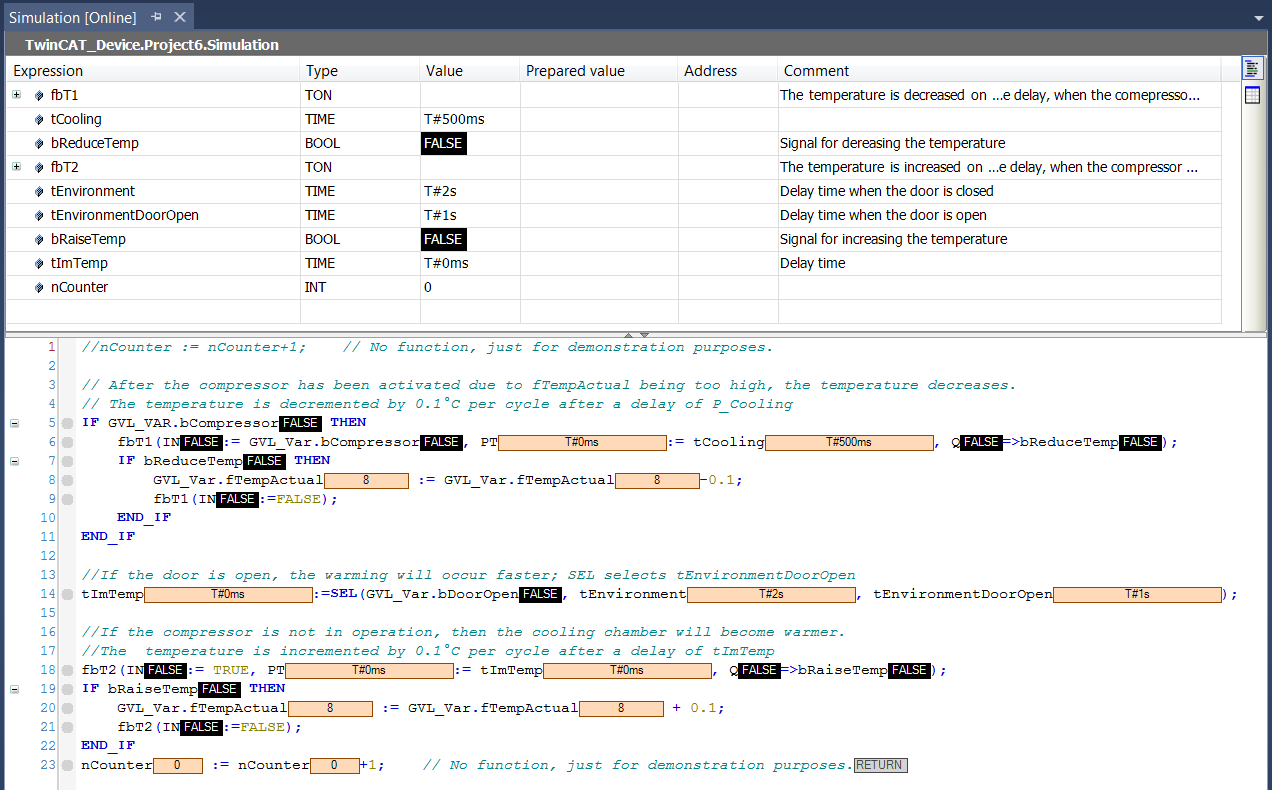
- The monitoring in the implementation part depends on the implementation language: For non-Boolean variables, the value is always in a rectangular field to the right of the identifier. In the ST editor, this also applies to Boolean variables. This display is named "Inline Monitoring". In the graphical editors, the value of a Boolean variable is indicated by the color of the output link line: black for FALSE, blue for TRUE:
- Note how the variable values in the different function blocks change. For example, the global variable list "GVL_Var" shows how the values of "fTempActual" and "bCompressor" change when the simulation program is executed.
One-time setting of variable values on the controller:
- 1. Set the focus to the online view of the global variable list "GVL_Var".
- 2. To specify a new setpoint, double-click the column Prepared value under the expression "fTempSet".
- An input field opens.
- 3. Enter the value "9" and exit the input field.
- 4. To set the door to open, click once in the Prepared value field of the "bDoorOpen" expression.
- The value TRUE is entered.
- 5. Click three more times to see that you can use this to set the prepared value to FALSE, then to empty again and then to TRUE again.
- 6. To write the prepared value TRUE once to the variable, select the command Write values in the PLC menu or click
 in the TwinCAT PLC Toolbar Options.
- The two values are transferred to the Value column. The variable "bDoorOpen" no longer changes its value and the set temperature is now 9 degrees. The variable "tImTemp" changes to the value 1 s, because the refrigerator door is now "open" and thus the heating by simulation should be faster than before (2 s).
Setting breakpoints and step-by-step execution at runtime
Debugging: For troubleshooting, you want to check the variable values at certain code positions. To do this, you can define breakpoints for processing and initiate step-by-step execution of the instructions.
- The PLC program is loaded onto the controller and is running.
- 1. Double-click the "Simulation" object to open the program in the editor.
- 2. Place the cursor in the code line
nCounter:=nCoutner+1;and press [F9]. - The symbol
 appears before the code line. It indicates that a breakpoint is set at this line. The symbol immediately changes to
  . The yellow arrow always points to the next instruction to be executed.
 - 3. Consider the value of the variable "nCounter" in the inline monitoring or in the declaration part of the Simulation program.
- The variable value no longer changes. The execution was stopped at the breakpoint.
- 4. Press [F5] to restart the execution.
- The program stops again at the breakpoint after one cycle. "nCounter" was incremented by 1.
- 5. Press [F11] to execute the next step
- RETURN at the end of the line
nCounter:=nCounter+1;the instruction is highlighted in yellow - 6. Press [F11] again to execute the next step.
- The execution jumps to the editor of MAIN. Pressing [F11] repeatedly shows how the program is executed step-by-step. The instruction to be executed is again marked with a yellow arrow.
- 7. To disable the breakpoint and return to normal execution, move the cursor into the code line again and press [F9]. Then press [F5] to restart the program execution.
- You can run through the program step-by-step and check variable values at certain code positions.
Executing a single cycle at runtime
- The PLC program is loaded onto the controller and is running.
- 1. Observe the line
nCounter:=nCounter+1;again in the Simulation program. - 2. Click
 in the TwinCAT PLC Toolbar Options to execute a single cycle.
 - The execution runs through a cycle and stops again at the breakpoint. "nCounter" was incremented by 1.
- 3. Click the button three more times to see the individual cycles. Then press [F5] again.
- The program runs again without stop and without forced values. The variable "tImTemp" has the value 1 s again.