Programming in the Ladder editor
The prerequisite for programming in Ladder:
You have created a programming block in the Ladder implementation language in your project. You have opened this box for editing in the Ladder editor.
The following instructions describe only individual actions when working in the editor. No specific program is created. If needed, also see the following chapter: Navigation in the Ladder editor
Inserting, repositioning, and modifying elements in a network
Insert elements into networks:
- 1. For example, in the toolbox (Tools window) of the editor, select the Contact element.
- 2. Drag it to the network with the mouse and hold the mouse button.
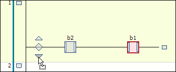
- When you drag across the network, possible insertion positions are indicated by the following symbols:
Square with gray background inside an existing element symbol
Rhombus on a connecting line
Triangle, pointing down or up, for insertion above or below - 3. You can insert the contact element when the mouse cursor gets a plus symbol
 .
. 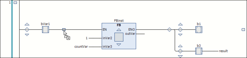
- 4. Release the mouse button at such a position.
- The contact is inserted in the processing line of the network.
Insert boxes:
- 1. Add an element Box in the network.
- 2. Replace the three question marks ??? in the element box with the name of the desired box from the project or a library.
- 3. To do this, double-click the question marks and ideally use the Input Assistant by clicking the
 button.
- The box is inserted and given the appropriate name.
Update boxes:
For example, if you call a function block from your project in the Ladder, you must also update in the ladder diagram after a change to the base FB.
 | A corresponding "Update" command is currently not yet available. |
Insert inputs:
- 1. Insert an input before the box.
- 2. To assign variables, replace the three question marks ??? at the element with the variable name.
- If necessary, the standard dialog Auto Declare, Select, Reposition opens.
Reposition elements in the network:
- 1. Select an element so that it is displayed with a red background. In the case of a box, the square inside the box icon has to be displayed with a red background.
- 2. Drag the element to another possible insertion position until the cursor symbol gets a square and release the mouse button.
- The element is positioned accordingly.
Replace elements:
- 1. To replace an existing element with another, drag the new element onto the one you want to replace.
- 2. Release the mouse button when the element to be replaced itself lights up green as an insertion point.
- The element is replaced.
Add new network:
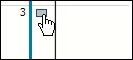
- 1. Drag the Network element to the implementation part.
- You will get rectangular insertion marks in the left margin area where the network numberings are displayed. The new network is inserted above the selected insertion point.
Modify networks:
Provide elements in the network with modifiers:
- 1. Select the input pin of a box.
- 2. Right-click to open the context menu.
- 3. Select the Negate command to negate an input, or one of the Set/Reset or Edge Detect commands (Command: Edge Detection: Rising Edge, Command: Edge detection: Falling edge).
- The input is assigned the corresponding symbol.
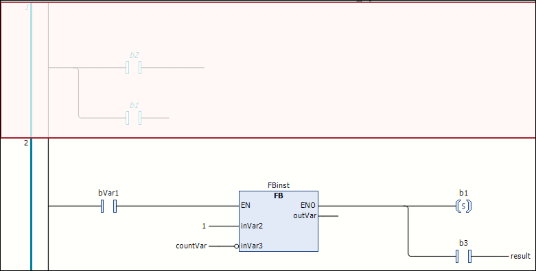
Example: Negated input on the box, set coil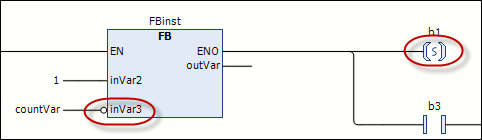
Creating and editing line branches
Unlike the LD/FBD editor, there are no elements for line branches in the Ladder editor. You create and edit branches simply by positioning or repositioning elements. Examples:
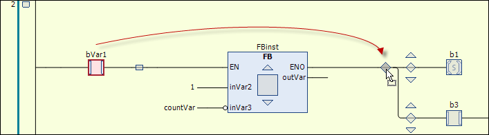
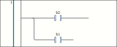
- 1. Create the following network:
- 2. Drag the second contact to the insertion position marked with a downward pointing arrow in front of the first contact.
- A parallel branching open to the rear is formed. Each branch contains one contact.
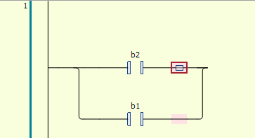
To create a closed line branch from the open line branch, i.e. to program an OR construct, proceed as follows:
- 1. Select both branches behind the contact element (multiple selection).
- 2. The selection is indicated by the small square with a red background on the line.
- 3. Then select the Close parallel branch command.
- The two parallel branches open at the end become a closed branch.
There are two ways to reopen the closed branch:
- You select one of the two branches and drag the selection box to that of the other branch.
- You select both branches and select the command Open parallel branch.
| If closed line branches have several parallel branches, the Open parallel branch command will always open all branches. |
Comment out network
- 1. Select a network so that it is completely displayed with a red background.
- 2. Select the Commented out command from the context menu.
- The network contents are displayed in gray and the texts in italics. The network is not taken into consideration during processing.
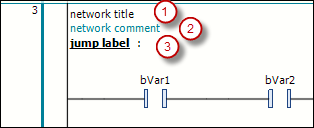
Add network title, network comment, jump label
You can add a network title (1), a network comment (2), and/or a jump label (3) to a network.