General FMMU / SM
Data Link Layer
The Data Link Layer links the application layer and the physical layer. The EtherCAT slave controller is located in the Data Link Layer and handles EtherCAT communication as an interface between the EtherCAT fieldbus and the slave application. At the physical level, data from the EtherCAT Slave Controller is converted into electrical or optical signals. The EtherCAT State Machine runs in the application layer. At the application layer, service data objects and process data objects are used and changed. File access and network communication control the application layer.
FMMU
The abbreviation FMMU stands for Fieldbus Memory Management Unit. An FMMU belongs to the Data Link Layer and can be found in each I/O terminal. FMMUs are used to map logical addresses bitwise or bytewise to physical addresses of the EtherCAT Slave Controller.
In the start-up phase, the master configures the FMMUs of each slave and specifies which area of the logical process data image is to be assigned to which local address space. Each FMMU channel maps a continuous logical address range to a continuous physical address range of the slave device. While the telegram passes through the device, the FMMU can take certain data for the terminal and also insert data into the telegram. The telegram is delayed only a few nanoseconds if the slave device is not connected to the EtherCAT telegram via a connector.
SyncManager
A SyncManager protects a DPRAM area from simultaneous access and thus ensures data consistency. A three-buffer SyncManager is usually used for process data communication, and a one-buffer SyncManager is usually used for non-process data communication. The three-buffer SyncManager is referred to as a buffered-type SyncManager. It always has a free buffer for writing and always, except before the first write, a consistent buffer for reading. The one-buffer SyncManager is referred to as a mailbox-type SyncManager. It implements data overflow protection. The write side must write before the read side can read; the read side must read before the write side can write again.
SyncManagers ensure a consistent and secure data exchange between the EtherCAT master and the local application of a slave device. The EtherCAT master configures the SyncManager of each slave device; it determines the direction and method of communication. A data buffer is available for data exchange.
In buffered mode, the EtherCAT master and slave application can access the data buffer at any time and simultaneously read and write data without data conflicts. The most recent consistent data buffer can be read at any time, and the data buffer can be written to at any time. If write is faster than read, older data is lost. The buffered mode is usually used for cyclic process data communication.
For the 3-buffer mode, 3 buffers of identical size are physically used. The start address and size of the first buffer is configured in the SyncManager configuration. The addresses of this first buffer are used by the master device and by the local application to read and write the data. Depending on the state of the SyncManager, accesses to the address range of the first buffer are redirected to one of the three buffers. Therefore, other SyncManagers must be configured such that they do not access the memory area of the second and third buffers.
One of the three buffers is assigned to the producer for writing. One of the three buffers is assigned to the consumer for reading. One of the buffers keeps the data written by the producer consistent.
In mailbox mode, only one buffer with a previously configured size is used and there is a handshake for data exchange between the EtherCAT master and the local slave application. First, the mailbox buffers can be written to after initialization. After the write operation has been completed, write access is locked and the buffer can be read from the other side. The read or write process has to be sequential, and only one of the two, the EtherCAT master or the local application, is granted access to the data buffer. While one is writing, the other may not read; while one is reading, the other may not write. You may only write to the data buffer again when everything has been read out, so that nothing is overwritten and no data is lost and all data from the producer reaches the consumer. Mailbox mode is usually used for protocols of the slave application layer.
FMMU/SM
The "FMMU/SM" dialog shows the current configuration of the FMMUs and SyncManagers and allows the user to change these settings.
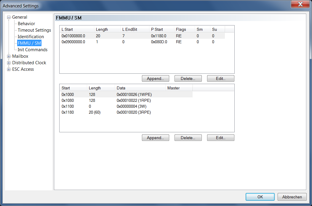
The upper list shows the configuration of the FMMUs.
|
Column |
Description |
|---|---|
|
L Start |
Specifies the logical address from which the FMMU starts mapping the data. The start bit is set according to the number following the dot. (0xnnnnnnnn.StartBit.) |
|
Length |
Specifies how many bytes are mapped by logical addressing. |
|
L EndBit |
End bit of the logical address. If the logical address is to be configured to one byte, the start bit must be set to 0 (L Start = 0xnnnnnnnn.0), and this entry must be set to 7. |
|
P Start |
Defines the physical address to which the logical address points. |
|
Flags |
RE: Read Enabled. |
|
Sm |
The command shown in the example belongs to Sync Manager 0. |
|
Su |
The command shown in the example belongs to Sync Unit 0. |
The lower list shows the configuration of the Sync Manager.
|
Column |
Description |
|---|---|
|
Start |
Determines from which address the Sync Channel is active. |
|
Length |
Length of the Sync Channel in bytes. If the length is 0, the Sync Channel is not enabled. |
|
Data |
Configuration data written to the SyncManager. The expression in parentheses starts with the number "1" or with the number "3". Number "1" means that the corresponding Sync Channel operates in 1-buffer mode, number "3" means that the corresponding Sync Channel operates in 3-buffer mode. The 1-buffer mode is also called mailbox mode. |
|
Master |
|