Distributed Clocks
Distributed clocks
Distributed clocks ensure that digital outputs can be updated synchronously and that digital inputs can be acquired synchronously. They allow incoming events to be allocated an exact time stamp (latch signals), synchronous output signals (sync signals) to be generated, and synchronous interrupts to be created.
There are DC devices that have their own system time, which enable the full functionality offered by distributed clocks. Furthermore, there are EtherCAT slave devices that have a local clock but only support the measurement of runtime delays. Devices with three or more ports must have at least this reduced functionality built in. Finally, there are slaves with no integrated DC functionality. They have a maximum of two ports, and their delay time is treated like the delay on a simple electrical line.
The distributed clocks are synchronized between the EtherCAT devices. A reference clock is specified for synchronization. Typically, the first DC device after the master manages the reference time. The EtherCAT master uses its clock to initialize the reference clock. Subsequently, however, the EtherCAT master is also synchronized based on this reference clock.
All local clocks initially run independently of the reference clock. The local clocks of the DC devices are synchronized with the reference clock in three steps, so that eventually each DC device has the system time. First, the delay time between the local clocks is measured. Next, the offset of the DC device clocks with respect to the reference clock is compensated. Finally, the drift between the local system time and the reference clock is corrected on a regular basis.
The master sends out a frame to measure the delay time. With the help of the distributed local clocks, times are determined at which the transmitted frame reaches the ports of the slaves, and corresponding time stamps are assigned. In this way, runtime differences are measured between the ports of the slaves. The master reads all time stamps and calculates the delay times between all devices according to the topology of the EtherCAT network.
Once the delay time in the EtherCAT network is known, the system time can be distributed to the DC devices. The local time of each DC device is compared with the system time of the reference clock. The difference from this comparison is compensated by writing it individually to each DC device. All DC devices receive the same system time.
The drift between the reference clock and the local clock of a DC user must be compensated regularly. For this purpose, time differences to the DC subscribers are measured, and local clocks are reset.
External Mode
As a default setting, the first slave device in a master/slave system that needs DC support sets the reference clock. The external mode is used to synchronize two or more separate master/slave systems. One way to set up the external mode is to use the EL6692 terminal. This terminal can be inserted into the Sync Master system, for example. Starting from the Sync Master system, several Sync Slave systems can then be synchronized. The Sync Master system calculates a common clock-synchronous reference signal from the reference signals of the separate systems.
Distributed Clocks
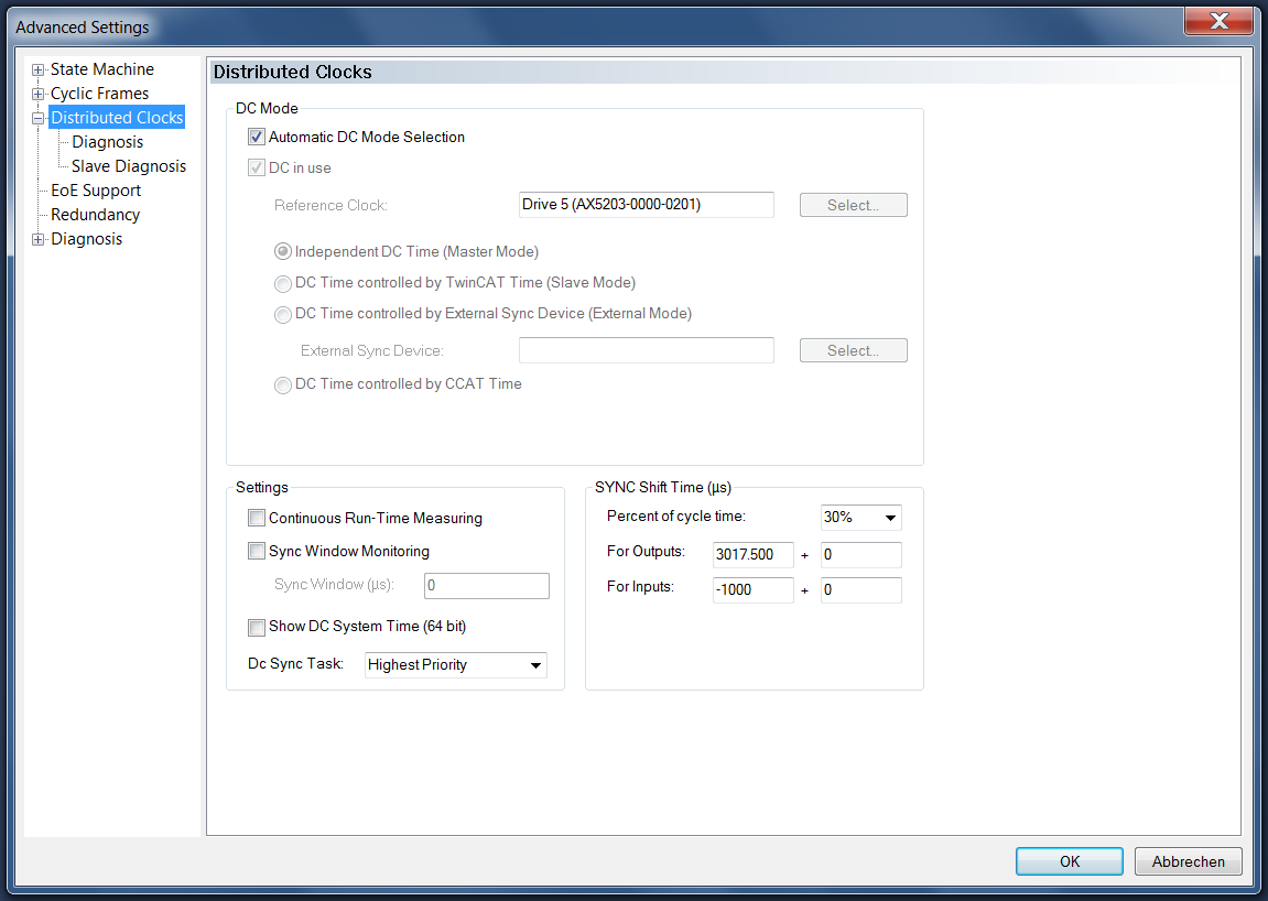
DC Mode
Automatic DC Mode Selection: This checkbox is checked by default. The Reference Clock is selected automatically.
DC in use: If this checkbox is checked, the reference clock and synchronization direction can be selected manually. If only one EtherCAT device is present in the configuration and if DC slave devices are used, "Independent DC Time (Master Mode)" must be used as synchronization direction (exception: external synchronization).
Reference Clock – Select…:Usually the first EtherCAT device that supports distributed clocks (DC) functionality is entered in the text box. The "Select…" button currently has no function. The slave device settings determine the selection of the reference clock. Note the description for "Use as potential Reference Clock" in the slave device settings.
Independent DC Time (Master Mode): One of the EtherCAT devices, usually the first EtherCAT device that supports distributed clocks (DC), is the Reference Clock. All other DC devices are readjusted to this EtherCAT device.
DC Time controlled by TwinCAT Time (Slave Mode): The DC Reference Clock is readjusted to the local TwinCAT time. This setting is used in cases where several EtherCAT systems with distributed clocks function are operated in the same control system. However, this tracking mode has reduced accuracy. If high accuracy is required the external CU2508 EtherCAT hub must be used.
DC Time controlled by External Sync Device (External Mode): If the EtherCAT system is to be readjusted according to a higher-level clock, an external clock can be selected under "External Sync Device – Select…".
DC Time controlled by CCAT Time: The reference clock of the CCAT device is used to control the distributed clock time. CCAT is a proprietary Beckhoff software interface and a hardware interface for various bus systems. (The CCAT interface can address the E-bus or the K-bus, for example.)
Settings
Continuous Run-Time Measuring: If this checkbox is checked, the time intervals between the devices are measured cyclically during the runtime. This process also takes place during EtherCAT start. We recommend to disable this function.
Sync Window Monitoring: If this checkbox is checked, bit 12 (0x1000) of the EtherCAT input variable "DevState" indicates whether all DC devices keep their local clocks within the window specified in the "Sync Window (µs)" text box. To measure the time, a cyclic BRD command on x092C (register in the EtherCAT slave. System time difference. Contains control errors in nanoseconds) is used. The "DC not in sync" display can only be utilized if the first EtherCAT device also contains the Reference Clock.
Sync Window (µs): This editable text box contains the time window in which all DC devices must maintain their local clocks in order to be "in sync". If the "Sync Window Monitoring" checkbox is checked, a value of 2 µs is automatically entered in the text box.
Show DC System Time (64 bit): If this checkbox is checked, the "DcSysTime" input variable of type UDINTARR2 is added to the inputs of the EtherCAT master. It displays the current DC time as a copy from the master clock. Reading the DC time consumes resources from the fieldbus transport. Alternatively, PLC function blocks can be used to ascertain the current DC system time.
Dc Sync Task: The task for controlling the distributed clocks can be selected from the drop-down list.
SYNC Shift Time (µs)
Percent of cycle time: In the example, the first summand for the outputs is about 30% of the cycle time. The frame lengths and delays of the individual slaves are included in the shift time.
For Outputs: The first summand contains the shift time that is automatically calculated by TwinCAT for all EtherCAT slave devices declared as an output module. The user can use the second summand to intervene and shift the PDI pulses by positive or negative time values.
For Inputs: The first summand contains the shift time that is automatically calculated by TwinCAT for all EtherCAT slave devices declared as an input module. The user can use the second summand to intervene and shift the PDI pulses by positive or negative time values.