Online
EtherCAT State Machine
With logical addressing, a section from the logical process image is addressed. A partial process image can be assigned to a task and synchronized with it.
Fieldbus Memory Management Units (FMMUs) map logical addresses to physical addresses of their EtherCAT device. This mapping can be read, write or both. SyncManagers ensure a consistent and secure data exchange between the EtherCAT master and the local application of a slave device.
The EtherCAT fieldbus is regarded as a logical memory. The physical memory of the slave device contains the process data. An FMMU correlates the logical memory with the physical memory, based on an allocation table.
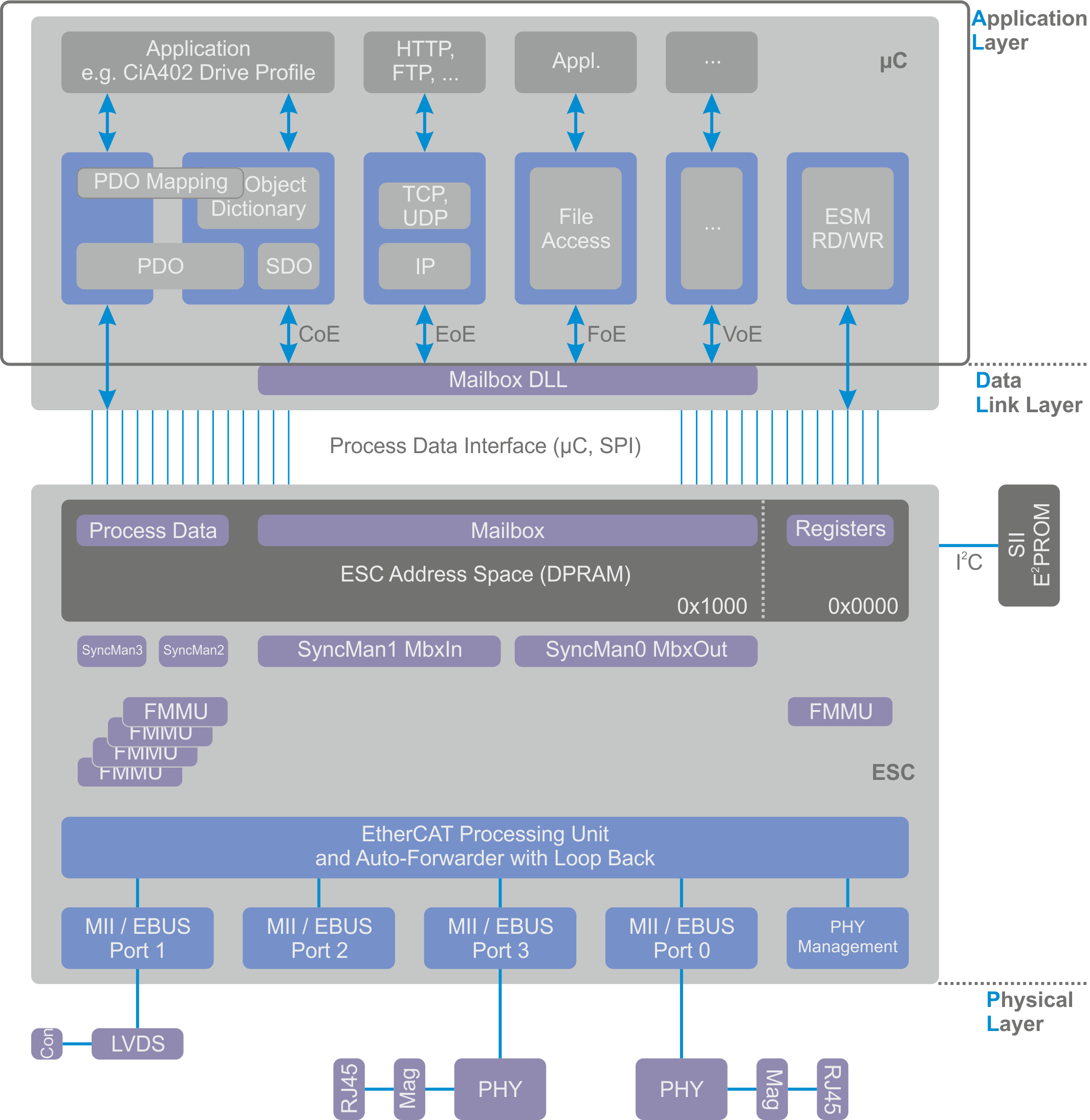
The EtherCAT state machine runs in the application layer, where process data objects are processed and file access and network communication are controlled. In the physical layer, data is converted into electrical or optical signals. The data link layer contains the FMMUs and the SyncManagers and links the physical layer to the application layer.
Distributed clocks enable synchronous generation of output signals and synchronous acquisition of input signals. With distributed clocks, events can get an exact time stamp. The distributed clocks in the local DC EtherCAT devices are synchronized. The offset and drift of the distributed clocks is compensated in relation to a reference clock. The delay time of the EtherCAT signal is determined and also compensated between the reference clock and the local clock.
The EtherCAT state machine (ESM) coordinates master and slave applications during start-up and operation. Changes of state in the slave device are usually requested by the master. In some cases, changes of state in the local application take place independently in the slave device. To switch from the Initialization state to the Operational state, an EtherCAT device first passes through the Pre-Operational state and then the Safe-Operational state.
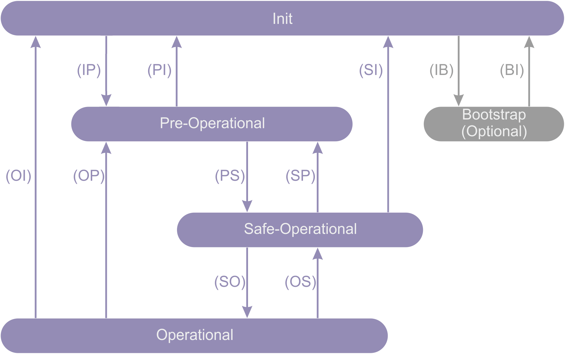
In the Init state, no communication takes place at the application level. The master has access to the registers of the data link layers that inform it.
The master requests the Pre-Operational state at the transition from the Init state to the Pre-Operational state. The master configures the channels of the SyncManagers for the mailbox communication and initializes the synchronization of the distributed clocks.
In Pre-Operational state, mailbox communication takes place on the application layer, but no process data communication takes place at this stage.
The master requests the Safe-Operational state at the transition from the Pre-Operational state to the Safe-Operational state. The master uses mailbox communication to set parameters for mapping process data, configuring the channels of the SyncManagers for the process data communication and the channels of the FMMUs.
Process data communication takes place in the Safe-Operational state. Inputs are read, outputs are not yet written.
The master requests the Operational state at the transition from the Safe-Operational state to the Operational state. The master sends valid values for the outputs.
In the Operational state, the outputs have valid values and the inputs continue to be evaluated as in the Safe-Operational state.
The Bootstrap state is only reached via the Init state and is only exited again towards the Init state. The Bootstrap state is recommended for firmware updates. In this state mailbox communication takes place at the application level, but only the File-Access-Over-EtherCAT protocol is available. No process data communication takes place in the Bootstrap state.
In the I/O tree, the variable "State" in the "InfoData" folder indicates the state of a slave device.
|
Value of the "State" variable |
State |
|---|---|
|
0x___1 |
Slave device is in "Init" state. |
|
0x___2 |
Slave device is in "PreOp" state. |
|
0x___3 |
Slave device is in "Boot" state. |
|
0x___4 |
Slave device is in "SafeOp" state. |
|
0x___8 |
Slave device is in "Op" state. |
|
0x001_ |
Slave device signals error. |
|
0x002_ |
Invalid vendor ID, invalid product code … read. |
|
0x004_ |
Initialization error occurred. |
|
0x008_ |
Slave device disabled. |
|
0x010_ |
Slave device not present. |
|
0x020_ |
Slave device signals connection error. |
|
0x040_ |
Slave device signals missing connection. |
|
0x080_ |
Slave device signals unexpected connection. |
|
0x100_ |
Communication Port A. |
|
0x200_ |
Communication Port B. |
|
0x400_ |
Communication Port C. |
|
0x800_ |
Communication Port D. |
EtherCAT, "Online" tab
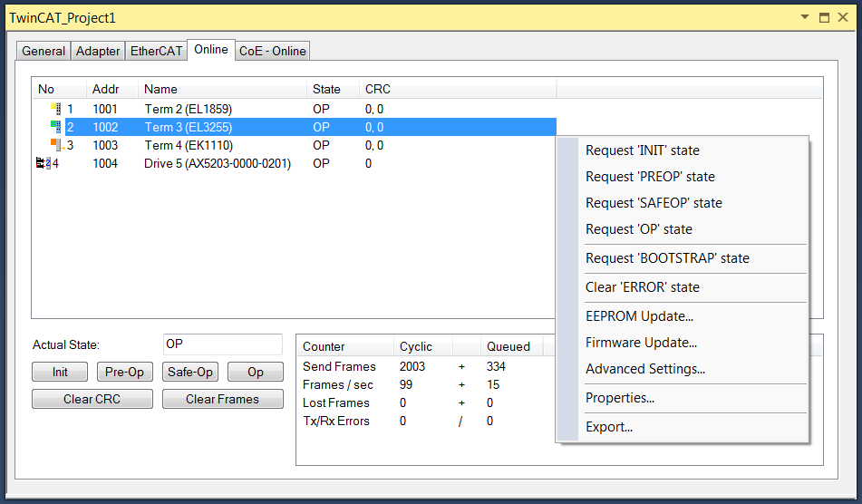
The "Online" tab becomes available when you are connected to the target system and select the EtherCAT device in the IO tree.
"Actual State" text box
The "Actual State" text box shows the current state of the EtherCAT master device.
"Init" button
The "Init" button requests the "Init" state from the EtherCAT master device.
"Pre-Op" button
The "Pre-Op" button requests the "Pre-Op" state from the EtherCAT master device.
"Safe-Op" button
The "Safe-Op" button requests the "Safe-Op" state from the EtherCAT master device.
"Op" button
The "Op" button requests the "Op" state from the EtherCAT master device.
"Clear CRC" button
The "Clear CRC" button clears the counters for the cyclic redundancy check of the EtherCAT slave devices.
"Clear Frames" button
The "Clear Frames" button sets the counters in the "Send Frames" table row to zero.
"Counter" column
The "Counter" column shows the counter type for the respective row.
"Cyclic" column
The "Cyclic" column contains information on cyclic EtherCAT communication.
"Queued" column
The "Queued" column contains information on acyclic EtherCAT communication.
"Send Frames" row
The "Send Frames" row contains information about sent transfer frames.
"Frames / sec" row
The "Frames / sec" row contains information about sent transfer frames per second.
"Lost Frames" row
The "Lost Frames" row contains information about lost transfer frames.
"Tx/Rx Errors" row
The "Tx/Rx Errors" row shows the data losses of the network card during sending and receiving.
EtherCAT slave devices list view
The list view at the top of the "Online" dialog shows all EtherCAT slave devices, their states and the values of the associated counters for the cyclic redundancy check.
"No" column
The "No" column provides information about the slave address of the device in the communication ring.
"Addr" column
The "Addr" column contains the fixed address (see EtherCAT Addr) of the EtherCAT slave device.
"Name" column
The "Name" column shows the name of the EtherCAT slave device.
"State" column
The "State" column indicates the state of the EtherCAT slave device. The state can be INIT, PREOP, SAFEOP or OP. Error states and intermediate information are also displayed.
"CRC" column
The "CRC" column shows the counter values for the cyclic redundancy check for one EtherCAT slave device at a time. The counters for the cyclic redundancy check of ports A, B (if used), C (if used) and D (if used) are listed one after the other, separated by dots. A cyclic redundancy check counter is incremented for the respective port if an error has occurred that has become apparent through the cyclic redundancy check. Frames can be destroyed or damaged while they pass through the network. Errors that become apparent through the cyclic redundancy check can be caused by cable faults, contact problems, loose contacts or loose connectors, for example.
Context menu in EtherCAT slave devices list view
Right-click in the list view of the EtherCAT slave devices to open a context menu. If no device is selected, the entries "Request 'INIT' state", "Request 'PREOP' state", "Request 'SAFEOP' state", "Request 'OP' state", "Request 'BOOTSTRAP' state", "EEPROM Update…" and "Advanced Settings…" are grayed out.
Context menu: Request 'INIT' state
This entry sets the selected slave device or devices to the "INIT" state.
Context menu: Request ‘PREOP’ state
This entry sets the selected slave device or devices to the "PREOP" state.
Context menu: Request ‘SAFEOP’ state
This entry sets the selected slave device or devices to the "SAFEOP" state.
Context menu: Request ‘OP’ state
This entry sets the selected slave device or devices to the "OP" state.
Context menu: Request ‘BOOTSTRAP’ state
This entry sets the selected slave device or devices to the "BOOT" state.
Context menu: EEPROM Update…

Notice | |
EEPROM Update Always check the compatibility between the EEPROM contents and the firmware version specified in the device documentation. |
Notice | |
EEPROM Update At the end of an EEPROM update, a hardware reboot must be performed. |
"Show Hidden Devices" checkbox
If the "Show Hidden Devices" checkbox is checked, older device descriptions with previous revision numbers are displayed.
"Browse…" button
The "Browse" button opens a dialog for searching and opening an EEPROM description file. A searched file is of type "EtherCAT Terminal Configuration (*.bin)".
"OK" button
The "OK" button writes the selected "EEPROM description" to the device and closes the dialog. If no "EEPROM description" has been selected, the "OK" button is grayed out.
"Cancel" button
The "Cancel" button closes the dialog without writing an "EEPROM description" to the device.
Context menu: Firmware Update…
The "Firmware Update…" context menu opens a dialog for searching and opening an EtherCAT firmware file. A searched file is of type "EtherCAT Firmware Files (*.efw)".
Context menu: Advanced Settings…
The "Advanced Settings…" entry opens the "Advanced Settings…" dialog for the selected terminal or slave device. It is grayed out if several devices are selected.
Context menu: Properties
The "Properties" entry refers not only to a selected entry in the list, but to the table as a whole. The "Properties" entry opens an "Advanced Settings" dialog, in which the online display can be extended with a wide range of information about the slave devices. This information is displayed in the list in an additional column. It is also possible to diagnose how many transfer frames have a jitter of a certain size. In Config mode, the slave devices can be rescanned and test transfer frames can be sent to them.
Context menu: Export…
The "Export…" entry opens a "Save as" dialog to save the table contents as a CSV file (text separated by semicolons). For the table shown in the screenshot, the name of the respective slave device, its physical address, its auto-increment address, its vendor ID, its production number, its revision number, its serial number, its state, its auto-increment offset, its counter for the cyclic redundancy check at port A, its counter for the cyclic redundancy check at port B, its counter for the cyclic redundancy check at port C and its counter for the cyclic redundancy check at port D are exported. The "INIT" state corresponds to a table entry 0x1, the "PREOP" state to a table entry 0x2, the "BOOT" state to a table entry 0x3, the "SAFEOP" state to a table entry 0x4 and the "OP" state to a table entry 0x8.