Distributed Clock Latch
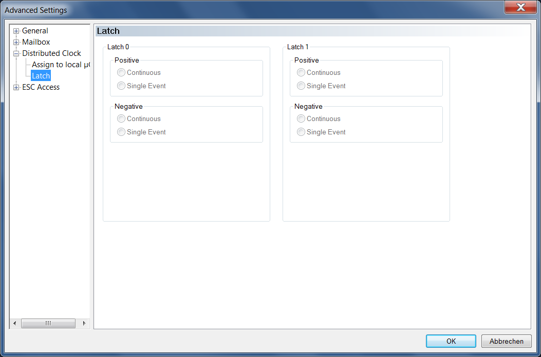
Two external signals, latch 0 and latch 1, can be assigned time stamps.
In "Single-Event mode" only the timestamps of the first rising (positive) or the first falling (negative) edge of the latch signal are recorded. Information about events that have occurred contains the latch state register 0x09AE for the latch0 signal and the latch state register 0x09AF for the latch1 signal. Latch time registers, which exist for the rising and for the falling edge, contain the time stamps associated with the events. In "Single-Event mode", each event is confirmed by reading out the corresponding latch time register. After a latch time register has been read out, the latch unit waits for the next event.
In "Continuous Mode" each event is stored in the latch time registers. During reading, the time stamp of the last event is read. In "Continuous mode" the latch state registers 0x09AE and 0x09AF do not reflect the states of the latch events.