Distributed Clock
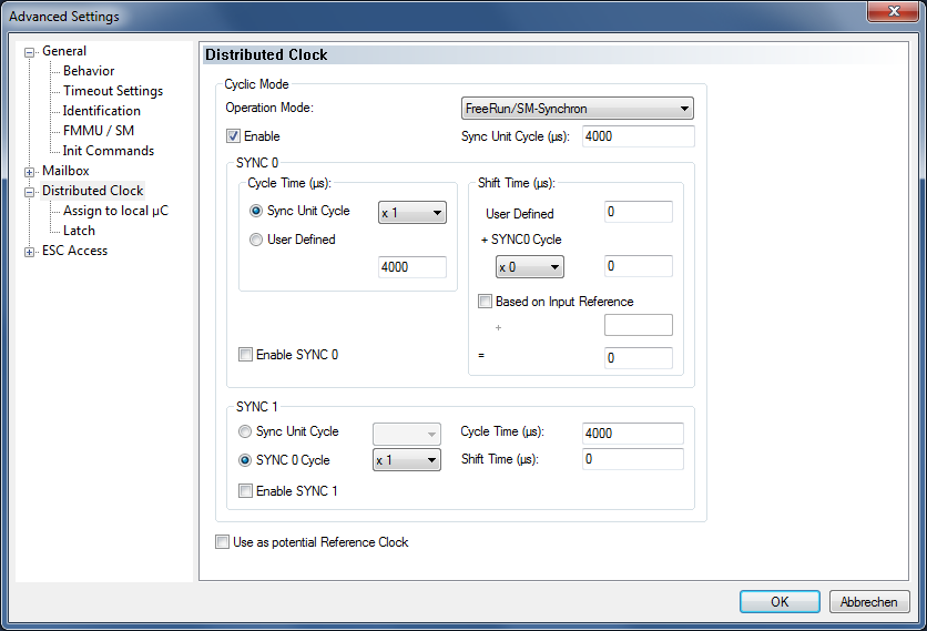
Operation Mode:
If an EtherCAT slave device offers several operation modes, then one of several operating modes can be selected here.
Cyclic mode/enable:
The checkbox enables the distributed clock functionality. If an EtherCAT slave device supports vendor-side distributed clock functionality, this option does not necessarily have to be enabled if the local clock is not required. In order to use an EtherCAT slave device as reference clock, the local clock of the slave device must be switched on with the "Enable" checkbox, even if distributed clock functionality is not required for the actual use of this slave device.
Sync Unit cycle (µs):
Basic cycle in the EtherCAT slave device. Corresponds to the EtherCAT cycle time that this EtherCAT slave device is currently handling. If several tasks with different cycle times are operated on one EtherCAT segment, then only the cycle time of the task that is in process data exchange with the slave device currently under consideration is displayed here. If several tasks are assigned to a slave device, the cycle time of the task with the highest priority to which a Sync Unit is assigned is displayed here.
Enable Sync 0:
Activates the SYNC 0 signal.
SYNC 0 – Cycle time (µs) – Sync Unit Cycle:
A multiple or a fraction of the basic cycle specified above can be set here. The result appears in the window below. At these intervals, the SYNC 0 signal is generated by the EtherCAT Slave Controller (ESC) when SYNC 0 and the distributed clock are activated.
SYNC 0 – Cycle time (µs) – User-defined:
Any value can be entered here.
Shift Time (µs):
The SYNC pulse of an EtherCAT slave can be shifted back or forth by a constant time.
Shift Time (µs) – User Defined:
Custom shift time. 0 by default.
Shift Time (µs) – SYNC0 Cycle:
Shift time as a fraction or multiple of the SYNC 0 cycle time.
Enable SYNC 1:
Activates the SYNC 1 signal.
SYNC 1 – Sync Unit Cycle:
The SYNC 1 cycle time can be derived from a multiple of the basic cycle.
SYNC 1 – Sync 0 Cycle:
The SYNC 1 cycle time can be derived from a multiple of the SYNC 0 cycle time.
SYNC 1 – Cycle Time (µs):
Here the result for the SYNC 1 cycle time is displayed.
SYNC 1 – Shift Time (µs):
Here a constant shift time between the SYNC 0 signal and the SYNC 1 signal can be entered in microseconds.
Use as potential Reference Clock:
If the "Use as potential Reference Clock" checkbox is checked, then this device becomes the reference clock if it is the first EtherCAT device which has activated this option after the master device and there is no DC device before it after the master device. It has no effect if DC devices are behind it.
The first DC device after the master device becomes the reference clock if there is no potential reference clock in the network. If a DC device is located in front of the potential reference clock, the first DC device after the master device becomes the reference clock.