General
To run EtherCAT you need a CPU, a compatible network card, a RJ45 cable and a slave device.
Real-time bus system
EtherCAT is a real-time bus system based on Ethernet technology. Inputs and outputs, sensors, drives and displays are all accessed directly via EtherCAT.
EtherCAT telegram
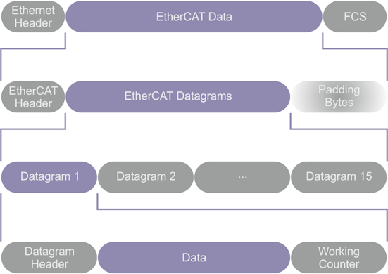
The EtherCAT telegram starts with an Ethernet header, followed by the EtherCAT data. The telegram is terminated by a frame check sequence (FCS). The EtherCAT data start with an EtherCAT header, followed by EtherCAT datagrams. If the entire Ethernet frame is smaller than 64 bytes, between 1 and 32 padding bytes are inserted at the end of the EtherCAT data. The EtherCAT data can contain up to 15 datagrams. A datagram consists of a header, the data to be read or written and a working counter.
"EtherCAT Header"
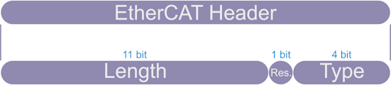
The "EtherCAT Header" is divided into a length specification, a reserved bit and a specification for the protocol type.
Field | Data type | Value/Description |
|---|---|---|
Length | 11 bits | Length of the EtherCAT datagram (without FCS) |
Reserved | 1 bit | Reserved, 0 |
Type | 4 bits | Protocol type. EtherCAT slave controllers (ESCs) only support EtherCAT commands (type = 0x1). |
EtherCAT datagram
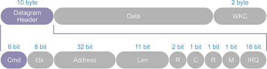
The "Datagram Header" contains information for the EtherCAT command type, a numerical identifier used by the master for identifying duplicates or lost datagrams, and an address specification. This is followed by a length specification indicating the length of the subsequent data within the datagram, two reserved bits, one bit to prevent circulating frames, another reserved bit, one bit to indicate whether another EtherCAT datagram follows, and finally an EtherCAT event request register.
Field | Data type | Value/Description |
|---|---|---|
Cmd | BYTE | EtherCAT command type |
Idx | BYTE | The index is a numerical identifier used by the master to identify duplicates or lost datagrams. The EtherCAT slaves should not change the index. |
Address | BYTE[4] | Address: auto-increment, configured station address or logical address |
Len | 11 bits | Length of the data following within this datagram |
R | 3 bits | Reserved, 0 |
C | 1 bit | Circulating frame: 0: Frame does not circulate 1: Frame has circulated once |
M | 1 bit | Multiple EtherCAT datagrams 0: Last EtherCAT datagram 1: At least one further EtherCAT datagram follows |
IRQ | WORD | EtherCAT event request register of all slave devices combined with a logical OR |
Data | BYTE[n] | Data to be read or written |
WKC | WORD | Working Counter |
Position addressing
Position addressing should only be used during start-up of the EtherCAT system to scan the fieldbus. Later, position addressing should only be used to detect newly added slaves.
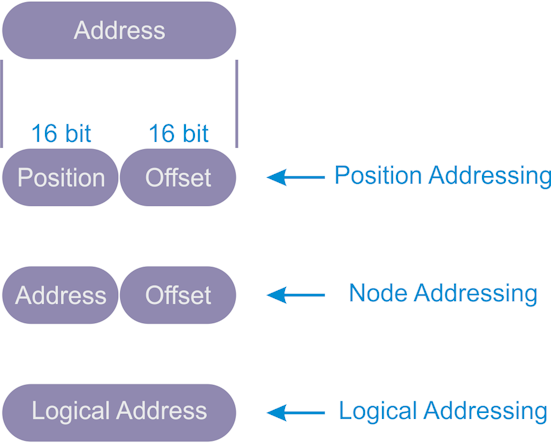
The datagram contains the position address of the addressed slave device as a negative value. Each slave increments this address. The slave that reads this address as zero is addressed and will execute the corresponding command as soon as it receives it.
Node addressing
Node addressing is typically used for register access to individual devices that have already been identified.
The configured station address is assigned by the master at start-up and cannot be changed by the EtherCAT slave. The Configured Station Alias address is stored in the ESI-EEPROM (ESI: EtherCAT slave information) and can be changed by the EtherCAT slave. The Configured Station Alias must be activated by the master. The respective command is executed if the node address either matches the Configured Station Address or the Configured Station Alias.
Mode | Field | Data type | Value/Description |
|---|---|---|---|
Position address / auto-increment address | Position | WORD | Each slave increments the position value. The slave is addressed if the position is 0. |
Offset | WORD | Local register address or local memory address of the ESC | |
Node address / configured station address and configured station alias | Address | WORD | The slave is addressed if its address corresponds to the Configured Station Address or the Configured Station Alias (if enabled). |
Offset | WORD | Local register address or local memory address of the ESC | |
Broadcast | Position | WORD | Each slave increments the Position field (which is not used for addressing). |
Offset | WORD | Local register address or local memory address of the ESC | |
Logical address | Address | DWORD | Logical address (configured by the FMMUs) The slave is addressed if the FMMU configuration corresponds to the Address field |
Broadcast addressing
Broadcast addressing is used for initializing all slave devices, for example.
Logical addressing
Logical addressing supports bitwise assignment of data. Logical addressing reduces unnecessary communication content in process data communication.
All devices read from and write to the same address range of the EtherCAT telegram. Each slave uses a mapping unit (FMMU, Fieldbus Memory Management Unit) to map data from the logical process data image to its local address and memory area. The master configures the FMMUs of each slave during start-up. By using the configuration information of its FMMUs, a slave knows which parts of the logical process data image are to be mapped to which local address area and memory area.
EtherCAT command types
The following table lists all supported EtherCAT command types. For combined read and write operations, the read operation is performed before the write operation.
Cmd | Abbreviation | Name | Description |
|---|---|---|---|
0 | NOP | No Operation | A slave ignores the command. |
1 | APRD | Auto Increment Read | A slave increments the address. A slave writes the data it has read to the EtherCAT datagram if the address received is zero. |
2 | APWR | Auto Increment Write | A slave increments the address. A slave writes data to a memory area if the address received is zero. |
3 | APRW | Auto Increment Read Write | A slave increments the address. A slave writes the data it has read to the EtherCAT datagram and writes the newly acquired data to the same memory area if the received address is zero. |
4 | FPRD | Configured Address Read | A slave writes the data it has read to the EtherCAT datagram if its slave address matches one of the addresses configured in the datagram. |
5 | FPWR | Configured Address Write | A slave writes data to a memory area if its slave address matches one of the addresses configured in the datagram. |
6 | FPRW | Configured Address Read Write | A slave writes the data it has read to the EtherCAT datagram and writes the newly acquired data to the same memory area if its slave address matches one of the addresses configured in the datagram. |
7 | BRD | Broadcast Read | All slaves write a logical OR of the data from the memory area and the data from the EtherCAT datagram to the EtherCAT datagram. All slaves increment the Position field. |
8 | BWR | Broadcast Write | All slaves write data to a memory area. All slaves increment the Position field. |
9 | BRW | Broadcast Read Write | All slaves write a logical OR of the data from the memory area and the data from the EtherCAT datagram to the EtherCAT datagram; all slaves write data to the memory area. BRW is typically not used. All slaves increment the Position field. |
10 | LRD | Logical Memory Read | A slave writes data it has read to the EtherCAT datagram if the address received matches one of the FMMU areas configured for reading. |
11 | LWR | Logical Memory Write | Slaves write data to their memory area if the address received matches one of the FMMU areas configured for writing. |
12 | LRW | Logical Memory Read Write | A slave writes data it has read to the EtherCAT datagram if the address received matches one of the FMMU areas configured for reading. Slaves write data to their memory area if the address received matches one of the FMMU areas configured for writing. |
13 | ARMW | Auto Increment Read Multiple Write | A slave increments the Address field. A slave writes data it has read to the EtherCAT datagram when the address received is zero, otherwise it writes data to the memory area. |
Working Counter
The Working Counter is incremented if an EtherCAT device was successfully addressed and a read operation, a write operation or a read/write operation was executed successfully. Each datagram can be assigned a value for the Working Counter that is expected after the telegram has passed through all devices. The master can check whether an EtherCAT datagram was processed successfully by comparing the value to be expected for the Working Counter with the actual value of the Working Counter after it has passed through all devices.
Command | Success | Increment |
|---|---|---|
Read command | No success | No change |
Reading successful | +1 | |
Write command | No success | No change |
Writing successful | +1 | |
Read/write command | No success | No change |
Reading successful | +1 | |
Writing successful | +2 | |
Reading and writing successful | +3 |
"EtherCAT slave controller"
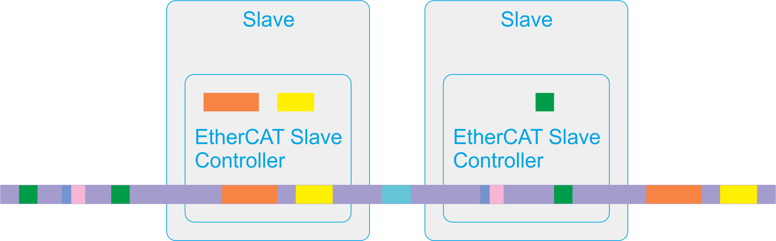
Each device sees the EtherCAT frame through a narrow data window. The data is read and written at runtime. Individual bits or even larger data packets can be taken from or inserted into the EtherCAT telegram.
Up to 65535 devices can participate in the data exchange. EtherCAT is flexible with regard to the topological arrangement of its devices: line, tree or star topologies can be configured and set up. A ring topology enables cable redundancy.
EtherCAT interfaces
An ASIC is an application-specific integrated circuit. The ET1100 ASIC, for example, is an EtherCAT Slave Controller (ESC). It handles EtherCAT communication as an interface between the EtherCAT fieldbus and the slave application. An FPGA is a field-programmable gate array.
Media Access Control (MAC) stands for station access to a communication medium. With full duplex Ethernet, any station can send data at any time. A Physical Layer Device (PHY) converts data from the Ethernet controller to electrical or optical signals. The Media Independent Interface (MII) is a standardized interface between an Ethernet Media Access Controller and a Physical Layer Device. RMII stands for Reduced Media Independent Interface.
The EtherCAT interfaces and ports connect the ESC with other EtherCAT slaves and the master. The MAC layer is an integral part of the ESC. The physical layer can be Ethernet or EBUS. The physical layer for EBUS is fully integrated in FPGAs or ASICs. For Ethernet ports, external Ethernet PHYs establish the connection to the MII/RMII ports of the ESC. The data transfer rate for EtherCAT is set to 100 Mbit/s with full duplex communication. The connection state and the communication state are communicated to the monitoring device. EtherCAT slaves support two to four ports. The logical ports are numbered 0-1-2-3, in TwinCAT they are assigned the letters A-B-C-D.
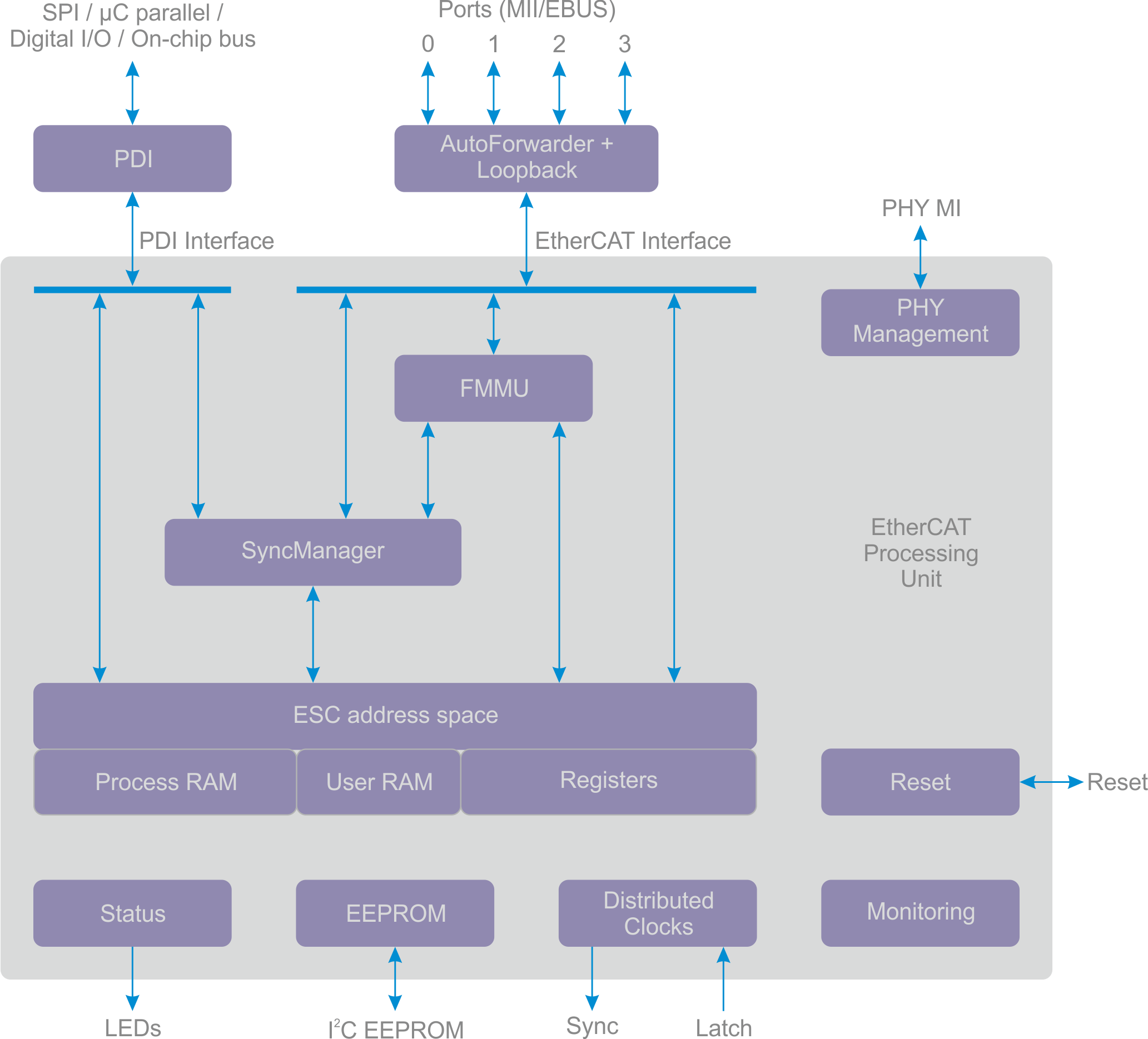
EtherCAT Processing Unit
The EtherCAT Processing Unit (EPU) receives, analyzes and processes the EtherCAT data stream. It is logically arranged between port 0 and port 3. The main purpose of the EtherCAT Processing Unit is to enable and coordinate access to the internal registers and to the memory area of the ESC. The memory area of the ESC can be addressed by the EtherCAT master and by the local application via the process data interface (PDI). Data exchange between the master application and the slave application is comparable to a memory (process memory) with two ports, in which the memory has been extended with special functions, for example for consistency check (SyncManager) or data mapping (FMMU). The EtherCAT Processing Unit contains the main function blocks of the EtherCAT slaves in addition to auto-forwarding, the loop-back function and the PDI.
Auto-Forwarder
The Auto-Forwarder receives the Ethernet frames, checks them and forwards them to the loop-back function. It also generates timestamps for the received frames.
Loop-back function
The loop-back function forwards Ethernet frames to the next logical port if one of the ports has no link, if the port is not accessible or if the loop for the port is closed. The loop-back function of port 0 forwards the frames to the EtherCAT Processing Unit. The loop settings can be controlled by the EtherCAT master.
FMMU
Fieldbus Memory Management units are used to map logical addresses bitwise to physical addresses of the ESC.
SyncManager
SyncManagers are responsible for consistent data exchange and mailbox communication between the EtherCAT master and the EtherCAT slaves. The communication direction can be set for each SyncManager. Read or write operations can generate events for the EtherCAT master and a connected microcontroller. The SyncManagers are responsible for the main difference between an ESC and a two-port memory because they map addresses to different buffers and block accesses, depending on the SyncManager state. This is also the fundamental reason for restrictions in the bandwidth of the PDI interface.
Monitoring
The Monitoring Unit contains function blocks for counting errors, and it contains watchdogs. The watchdogs monitor the communication. The error counters help to analyze errors.
Reset
The integrated reset controller monitors the power supply and controls external and internal resets. It is only available in the Beckhoff ET1100 ASICs and the Beckhoff ET1200 ASICs.
Distributed Clocks
Distributed clocks allow precisely synchronized generation of output signals, precisely synchronized reading of inputs and generation of time stamps for events. Synchronization can span the entire EtherCAT network.
Memory
An EtherCAT slave can have an address space of up to 64 kbytes. The first block of 4 kbytes, 0x0000-0x0fff, is used for registers and for user memory. The memory from address 0x1000 to address 60 kbytes is used as process data memory. The size of the process data memory depends on the device. The ESC address range can be addressed directly by the EtherCAT master or an attached microcontroller.
Process Data Interface
Depending on the ESC, there are several types of PDIs: Digital I/O, SPI slave, 8-16 bit microcontroller, on-chip bus, multi-purpose I/O.
ESI-EEPROM
A non-volatile memory is required for the ESC configuration and the device description.
State
The state block provides ESC information and application state information. It controls external LEDs, such as the application RUN LED, the application ERR LED, the port link LEDs or the port activity LEDs.