Adding Input/Output Modules (boxes)
In the tree view of the I/O configuration, the various input and output modules (boxes) are now added below the configured fieldbus cards, configured and, if necessary, linked to the variables of a PLC project or another runtime system (for example, an additional task).
A right mouse click on the configured I/O device opens a context menu. Different context menus are often also available for different fieldbus cards. Therefore, only the menu items that are common to all fieldbus cards are described below. For detailed device-specific information, please refer to the Technical Reference.
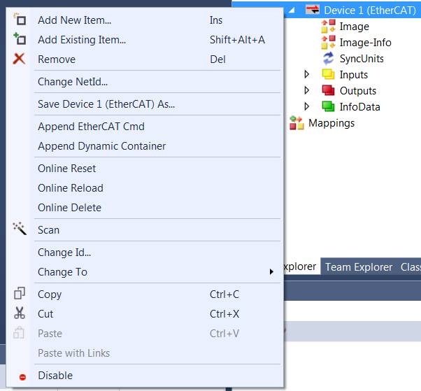
Add New Item…
Depending on the configured fieldbus system, "Add New Item…" calls up the selection dialog for the supported I/O modules.
Add Existing Item…
Integrates a fieldbus station into the current system that has been previously configured and exported.
Remove
Deletes the selected I/O device from the tree view and from the configuration.
Save "Device Name" as…
Saves the entire configuration with already attached boxes of the selected device to an export file.
Online Reset
Executes an I/O reset on the card. This is only possible when the configuration is active and the system is running.
Scan
Scans the device for lower-level boxes. Found boxes are listed in the tree view below the device. For the scan function, the target system whose boxes are to be found must be in configuration mode (Config mode).
Change Id…
A dialog box opens where the Id of the device can be changed in the configuration.
Change To
A selection pops up where a compatible device type can be selected.
Copy
Copies the selected I/O device to the clipboard.
Cut
Copies the selected I/O device to the clipboard and removes it from the I/O configuration.
Paste
Inserts a box from the clipboard in the last position in the configuration of the device.
Paste with Links
Inserts a box from the clipboard in the last position in the configuration of the device and, if possible, takes over already existing variable mappings.
Disable
Removes the selected device from the configuration calculation. The configuration of the deactivated station is retained with its link information and can be reactivated by pressing Disable again. This function is intended, among other things, for commissioning individual plant components. It also enables the combination of different devices in one control project, whereby the "Disable" function can be used to switch the respective existing device to active.