Dielectric strength
The output voltage is floating and has no ohmic connection to the ground.
The output is insulated to the input by a double or reinforced insulation.
Type and routine tests are conducted by the manufacturer. Field tests may be conducted in the field using the appropriate test equipment which applies the voltage with a slow ramp (2 s up and 2 s down).
- Connect all input-terminals together as well as all output poles before conducting the test.
- When testing, set the cut-off current settings to the value in the table below.
- When checking the input to DC-OK (see the following figure. B*)), make sure that the maximum voltage between DC-OK and the output is not exceeded (see column D in the table below). We recommend connecting DC-OK pins and the output pins together when performing the test.
- We recommend connecting either the positive pole or the negative pole to the protective earthing system. This helps to avoid situations in which a load starts unexpectedly or cannot be switched off when unnoticed earth faults occur.
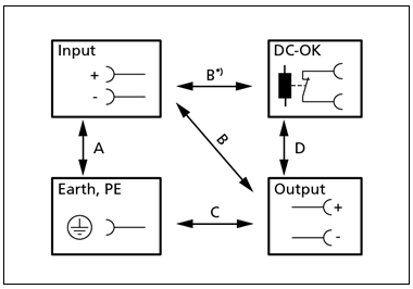 Fig.15: Dielectric strength
| A | B | C | D | |
|---|---|---|---|---|---|
Type test | 60 s | 1500 Vac | 1500 Vac | 500 Vac | 500 Vac |
Routine test | 5 s | 1500 Vac | 1500 Vac | 500 Vac | 500 Vac |
Field test | 5 s | 1000 Vac | 1000 Vac | 500 Vac | 500 Vac |
Cut-off current setting | > 20 mA | > 10 mA | > 80 mA | > 1 mA | |