DC input
The input can be powered from batteries or similar DC sources and must be a PELV or SELV source or an "Isolated Secondary Circuit" in order to maintain a SELV or PELV output.
DC input | |||
|---|---|---|---|
DC input | Nom. | DC 48 V | +/- 25 % |
DC input range |
| 36-60 Vdc |
|
Allowed voltage between input and ground | Max. | 60 Vdc or 42.2 Vac | according to IEC 62477-1 |
Allowed input ripple voltage | Max. | 10 Vpp | In the frequency range from 47 to 500 Hz, the momentary input voltage must always be within the specified limits. |
Turn-on voltage | Typ. | 35 Vdc | Steady-state value, see Fig. “Input voltage range” |
Shut-down voltage | Typ. | 32 Vdc | Steady-state value, see Fig. “Input voltage range” |
Input current | Typ. | 5.4 A | For 48 Vdc input and 24 V, 10 A output load, see fig. "Input current vs. Output load" |
7.5 A | For 36 Vdc input and 24 V, 10 A output load, see fig. "Input current vs. Output load" | ||
Inrush delay | Typ. | 200 ms | See Fig. “Input voltage range” |
Rise time | Typ. | 150 ms | At 24 V, 10 A constant current load, 0 mF load capacitance, see Fig. “Turn-on behavior, definitions” |
250 ms | At 24 V, 10 A constant current load, 5 mF load capacitance, see Fig. “Turn-on behavior, definitions” | ||
Turn-on overshoot | Max. | 500 mV | See Fig. “Turn-on behavior, definitions” |
Input capacitance | Typ. | 1,650 µF | Installed inside the device, external capacitors on the input are allowed without any limitations. |
Ext. input protection | See recommendations in chapter “Further notes on installation requirements” | ||
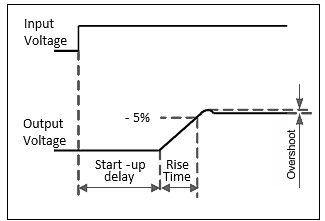 Fig.1: Input voltage range, Turn-on behavior, definitions
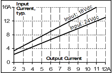 Fig.2: Input current vs. output load
Requirements for the Supplying Source
In certain circumstances, the input filter of the DC/DC converter can show a resonant effect which is caused by the supplying network. Especially when additional external input filters are utilized, a superimposed AC voltage can be generated on the input terminals of the DC/DC converter which might cause a malfunction of the unit. Therefore, additional input filters are not recommended. To avoid the resonant effects, the minimal resistance of the supplying network which depends on the inductance of the input network, shall be above the boundary curve in Fig. “External input filter requirements to avoid filter instabilities”.
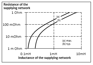 Fig.3: External input filter requirements to avoid filter instabilities