Parallel use for redundancy
1+1 Redundancy
Devices of the same Type PS9731-2410-0000 can be paralleled for redundancy to gain higher system availability. Redundant systems require a certain amount of extra power to support the load in case one device fails. The simplest way is to put two devices in parallel. This is called a 1+1 redundancy. In case one device fails, the other one is automatically able to support the load current without any interruption. It is essential to use a redundancy module to decouple devices from each other. This prevents that the defective unit becomes a load for the other device and the output voltage cannot be maintained any more.
1+1 redundancy allows ambient temperatures up to +70°C.
Pay attention that EMI and inrush current will increase when using multiple devices.
Recommendations for building redundant power systems:
- Use separate input fuses for each device.
- Use separate supply systems for each device whenever it is possible.
- It is desirable to set the output voltages of all devices to the same value (± 100mV) or leave it at the factory setting.
N+1 Redundancy
 | Notes on parallel use for N + +1 redundancy
|
Redundant systems for a higher power demand are usually built in a N+1 method.
E.g. four devices, each rated for 10 A, are paralleled to build a 30 A redundant system.
- Maintain an installation distance of 15 mm (left/right) between two devices.
- Do not install the devices on top of each other.
- Do not use devices in parallel in mounting orientations other than the standard mounting orientation or in any other condition, where a reduction of the output current is required.
Wiring example
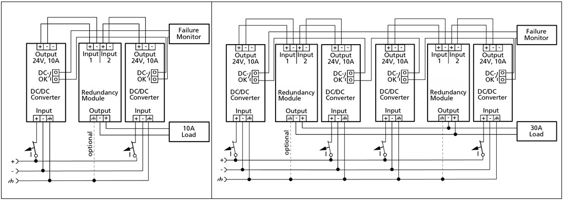 Fig.21: 1+1 Redundant configuration for 10 A load current; N+1 Redundant configuration for 30 A load current with multiple DC/DC converters and redundancy module