Input and output parameters
The device is designed to supply all kinds of loads, including unlimited capacitive and inductive loads. The input must be supplied from a PELV or SELV source in order to obtain a PELV or SELV output. Make sure the polarity of input and battery is correct. The device does not work if the voltage polarity is reversed.
Input and output parameters | |||
|---|---|---|---|
Number of inputs | - | 2 |
|
Number of outputs | - | 1 |
|
Input voltage | Nom. | DC 12-28 V | ±30% |
Input voltage range | - | 8.4-36.4Vdc |
|
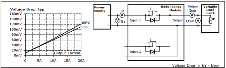
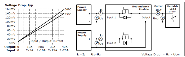
Voltage drop, input to output | Typ. | 72 mV | With 2x 10 A, see fig. 3 1 |
Typ. | 140 mV | With 2x 20 A, see fig. 3 1 | |
Input current | Nom. | 2x 0-20 A | Continuous operation |
Nom. | 2x 20-32.5 A | For maximally 5 seconds | |
Max. | 2x 32.5 A | With continuous overload or short circuit | |
Peak input current | Max. | 2x 1000 A | For up to 1ms max. |
Output current | Nom. | 40A | Continuous operation, ambient temperature below +70 °C |
Max. | 65A | For maximally 5 seconds | |
Overcurrent protection at the output |
| - |
|
Overload/short circuit current | Max. | 65 A (rms) | Make sure that the sum of the RMS input currents does not exceed this value. |
Reverse current | Max. | 1 mA | At 24 V, per input, -40 °C to +70 °C |
Reverse voltage | Max. | 40 Vdc | Permissible continuous voltage at the output |
Output capacity | Typ. | 320µF |
|
(typical 1+1 redundancy if the output voltages of both devices are identical)