Basics
Principle of operation
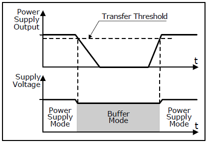
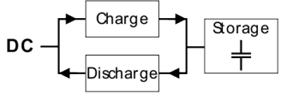
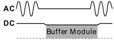
If the power supply unit supplies sufficient voltage, the buffer module stores energy in the integrated electrolytic capacitors. In case of a voltage drop or failure, this energy is fed to the DC link in a controlled manner.
Bridges power faults without interruption
Statistics show that 80% of all power faults last less than 0.2 s. These power faults are fully bridged by the buffer unit. This increases the reliability of the complete system.
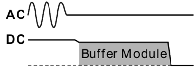
Extended hold-up time
Following a power failure or a power cut, the buffer unit maintains the load current for a defined timespan. Process data can be saved and processes ended before the DC voltage is switched off. A controlled restart is then possible.
Simple to handle, extendable and maintenance-free
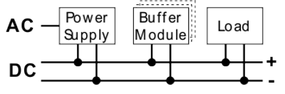
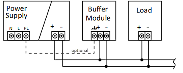
The buffer module requires no control wiring. It can be inserted anywhere in parallel with the load circuit. Buffer modules can be connected in parallel in order to increase the output current capacity or the hold-up time.