Terminals and wiring
The terminals are designed to be finger-safe according to IP20 and are suitable for field or factory wiring.
Technical data | Input | Output | DC-OK signal |
|---|---|---|---|
Connection cross-section | e*: 0.5 - 6 mm² f*: 0.5 - 4 mm² a*: max. 4 mm² (d<2.8 mm) | e*: 0.5 - 6 mm² f*: 0.5 - 4 mm² a*: max. 4 mm² (d<2.8 mm) | e*: 0.3 - 4 mm² f*: 0.3 - 2.5 mm² a*: max. 2.5 mm² (d<2.25 mm) |
Connection cross section (AWG) | e*: AWG 20-10 f*: AWG 20-10 a*: AWG 20-10 (d<2.8 mm) | e*: AWG 20-10 f*: AWG 20-10 a*: AWG 20-10 (d<2.8 mm) | e*: AWG 26-12 f*: AWG 26-12 a*: AWG 26-12 (d<2.25 mm) |
Strip length | 10 mm / 0.4 inch | 10 mm / 0.4 inch | 6 mm / 0.25 inch |
e* = solid wire
f* = stranded wire
a* = with ferrule
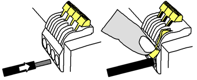
Wiring instructions:
- Use suitable copper cables that are designed for at least the following operating temperatures:
+60°C for ambient temperatures up to +45°C and
+75°C for ambient temperatures up to +60°C and
+90°C for ambient temperatures up to +70°C. - Observe the national installation rules and regulations!
- Make sure that all single wires of a strand are connected to the terminal!
- Do not use the device without PE connection.
- Ferrules are permitted.
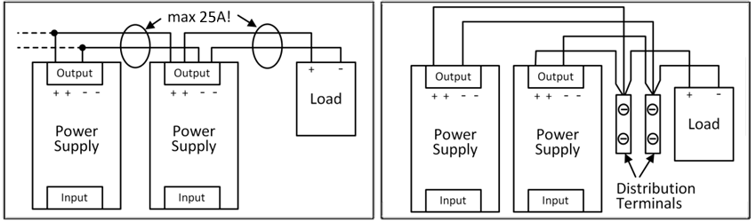
Series connection of power supply units:
Series connection (looping from one power supply output to the next) is permitted as long as the average output current flowing through a connection pin does not exceed 25 A. For higher currents please use a separate distribution terminal strip as shown in Fig. Using distribution terminals.