Front side and operating elements
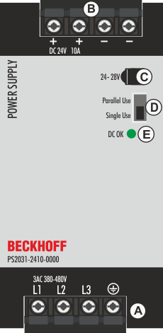
Input terminals (screw terminals)
Designation (A) | Description |
|---|---|
L1, L2, L3 | Mains input L1, L2, L3 |
| PE input (protective conductor) |

Output terminals (screw terminals)
Designation (B) | Description |
|---|---|
+ | two identical positive poles, positive output |
- | two identical negative poles, negative output |
Potentiometer for the output voltage
Designation (C) | Description |
|---|---|
Potentiometer cover | Open the flap to adjust the output voltage. Factory setting: 24.1 V |
"Parallel Use" or "Single Use" mode
Designation (D) | Description |
|---|---|
Jumper for "Single Use" | Set the jumper to "Parallel Use" if devices are connected in parallel to increase the output power. |
DC OK LED
Designation (E) | Description |
|---|---|
Push-in terminals | Monitors the output voltage of the active power supply. |