Output
The output provides an SELV/PELV nominal voltage that is electrically isolated from the input voltage.
The device is designed to supply any type of load, including capacitive and inductive loads.
The output is electronically protected against overload, no-load and short circuit. In the event of a protection event, audible noises may occur
Output voltage | Nom. | 24 V |
|
Adjustment range | Min. | 24-28V | Guaranteed value |
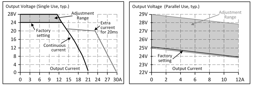
Max. | 30.0 V | This is the maximum output voltage that can occur in the end position of the potentiometer in clockwise direction due to tolerances. It is not a guaranteed value that can be achieved. | |
Factory settings | Typ. | 24.1 V | ±0.2%, single use at full load (cold device) |
Line regulation | Max. | 10 mV | Between 3x 323 and 3x 576 Vac |
Load regulation | Max. | 100 mV | Between 0 and 10 A, static value, single use |
Typ. | 1000 mV | Between 0 and 10 A, static value, parallel use, see Fig. Output voltage over output current (parallel use) typ. | |
Residual ripple and ripple voltage | Max. | 50mVSS | Bandwidth 20 Hz to 20 MHz, 50 Ohm |
Output current | Nom. | 12A1) | At 24 V and ambient temperature below 45°C |
Nom. | 10A | At 24 V and 60°C ambient temperature | |
Nom. | 7.5A | At 24 V and 70°C ambient temperature | |
Nom. | 10.3A1) | At 28 V and ambient temperature below 45°C | |
Nom. | 8.6A | At 28 V and 60°C ambient temperature | |
Nom. | 6.5A | At 28 V and 70°C ambient temperature | |
Linear derating between +45°C and +70°C | |||
Safety | Typ. | 23A | Up to 20ms once every five seconds, see Fig. Output voltage over output current, typ. |
Overload behavior |
| Continuous current | see Fig. Output voltage over output current, typ. |
Short circuit current | Max. | 23A | Continuous current, see Fig. Output voltage over output current, typ. |
Output capacity | Typ. | 6500μF | Included in the power supply |
Load feedback | Max. | 35V | The device is resistant to load feedback and will not indicate a malfunction if a load is feeding voltage back into the power supply. It does not matter whether the power supply is switched on or off. The absorbed energy can be determined by means of the built-in large-size output capacitor. |
1) This current is also available for temperatures up to +70°C with a duty cycle of 10% and/or no more than 1 minute every 10 minutes.