Front side and operating elements
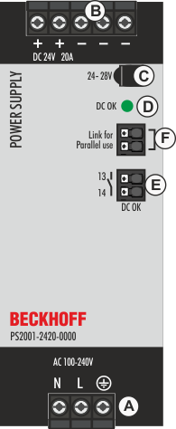
Input terminals (screw terminals)
Designation (A) | Description |
|---|---|
N | Mains input N |
L | Mains input L |
| PE input (protective conductor) |

Output terminals (screw terminals)
Designation (B) | Description |
|---|---|
+ | two identical positive poles, positive output |
- | three identical negative poles, negative output |
Potentiometer for the output voltage
Designation (C) | Description |
|---|---|
Potentiometer cover | Open the flap to adjust the output voltage. Factory setting: 24.1 V |
DC-OK LED
Designation (D) | Description |
|---|---|
LED green | Lights when the output voltage has reached 90% of the set output voltage. |
DC-OK relay contact
Designation (E) | Description |
|---|---|
Push-in terminals | Monitors the output voltage of the active power supply. |
"Parallel Use" "Single Use" connection
Designation (F) | Description |
|---|---|
Push-in terminals | Connect the two terminals when power supplies are connected in parallel. In order to achieve a distribution of the load current to the individual power supplies, the output voltage is regulated in parallel connection mode such that the voltage at no load is approx. 4% higher than at nominal load. See also chapter on Parallel use for power increase. |