SERCOS Measurement
Drive parameters
For use of the measurement function, the following parameters must be set in the drive:
- Real time control and status bits used
- Measuring probe to be used
- Measuring probe control parameters
- Measured value in the cyclic telegram
Refer to the drive documentation for details of the parameters supported by the relevant drive.
Additional it is possible that a digital input of the drive has to be configured as probe latch. Please refer here also to the documentation of the relevant drive.
Real time bits
For measurement both real time status bits and one real time control bits are necessary.
With the real time status bits the following information is transferred to the NC kernel:
- Edge at measurement input detected (measurement done)
- Measurement equipment actuated.
Also, a real time control bit is necessary to enable the edge detection of the probing input in the drive.
The assignment of the real time status and control bits used by the NC-kernel is done with P-AXIS-00060. Also drive parameters must be set accordingly.
The following table shows the assignment of the real time bits used by the NC-kernel dependent on the value of P-AXIS-00060.
P-AXIS-00060 | Control bits | Status bits | |
| Measurement | Measurement | Measurement equipment Actuated |
0, | Realtime control bit 1 | Realtime | |
1 | Realtime control bit 1 | Realtime | Realtime |
2 | Realtime control bit 2 | Realtime | Realtime |
 | It is recommended to set P-AXIS-00060 to either 1 or 2. The value 0 is just for backward compatibility with older versions of the NC-kernel and requires additional settings (P-AXIS-00106). |
Measuring probe control parameters
The measuring probe control parameter (S-0-0169) is used to configure which measuring probe and which edge of the measured signal is to be used in the drive. Depending on this parameter, the registered positions are stored in different SERCOS identifications, and these SERCOS identifications must then be transferred in the drive's cyclic actual value telegram.
Measuring probe/edge | Measuring probe control parameter | Measured value identification |
Measuring probe 1, positive edge | S-0-0169 = 1 | S-0-0130 |
Measuring probe 1, negative edge | S-0-0169 = 2 | S-0-0131 |
Measuring probe 2, positive edge | S-0-0169 = 4 | S-0-0132 |
Measuring probe 2, negative edge | S-0-0169 = 8 | S-0-0133 |
Parameterization of the cyclic telegram
The measured value identification specified in the table above must be configured in the cyclic actual value telegram depending on the measuring probe control parameter.
Axis parameters
For SERCOS drives, the following entries must be assigned in the axis parameter lists:
P-AXIS-00116 | Measurement via SERCOS bus:
|
P-AXIS-00113 | Latching if positive measured signal edge:
|
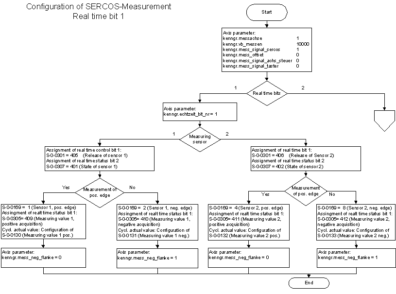
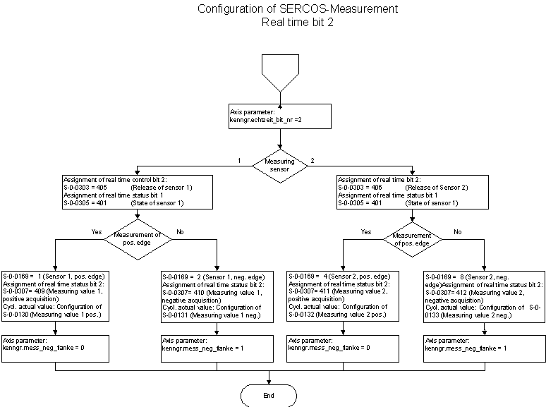
Parameterizing a SERCOS drive
The steps necessary to parameterize a SERCOS drive are presented in a flowchart on the following pages.
Example
The following parameters are necessary in the drive and in the NC kernel for configuration of the measuring function of a SERCOS drive with the rising edge of measuring probe 1 using the real time and status bits 1.
Axis parameters
kenngr.hub_messtaster      2000
kenngr.vb_messen           2000
kenngr.messachse           1
kenngr.mess_signal_sercos  1
kenngr.echtzeit_bit_nr     1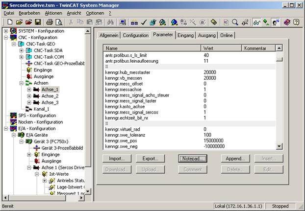
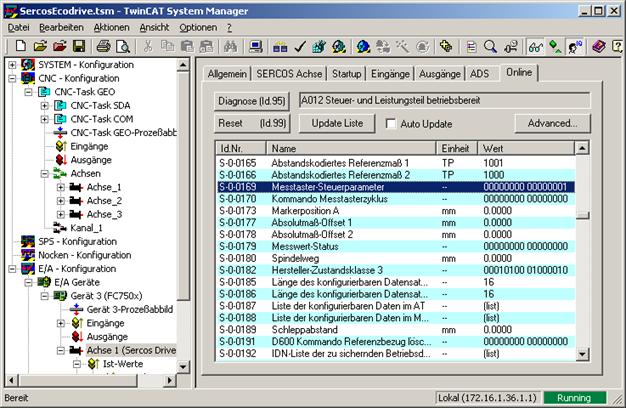
Cyclic telegram
Identification S-0-0130 must also be configured when configuring the cyclic telegram:
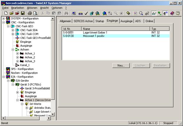
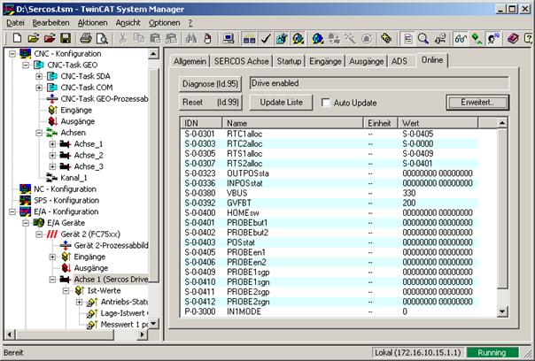
Drive
The real time bits 1 and measuring probe 1 are used:
- S-0-0301 = 405 (real time control bit 1 = measuring probe 1 enabled)
- S-0-0305 = 409 (real time status bit 1 = probe 1, positive latched)
- S-0-0307 = 401 (real time status bit 2 = measuring probe 1)
Measuring probe control word
Value 1 must be entered into the measuring probe control word:
- S-0-0169 = 1 (measuring probe 1 positive edge)