Programming
Measurement results
When measurement is performed via the NC command G100/G310, an axis position is stored after triggering of the measuring probe. After triggering of the measurement interrupt, the current position is stored (latched) and measurement travel is possibly ended.
The positions registered by measurement can be used in the NC program by means of the G101/G102 commands (calculation of the measurement offset) and the following axis-specific variables.
V.A.MESS.X Measured value of axis X
V.A.MERF.X Measurement has taken place (TRUE/FALSE),
specifying whether the measurement interrupt has
arrived before the target position has been reached
V.A.MOFFS.X Distance between measured position and
programmed target position
V.A.MEIN.X The actual measurement offset activated by G101 of the X-axis. This value acts as additive offset of the programmed position:
PCS = PCS + measurementoffsetG101
For further information on the measurement functionality, refer to the programming instructions [PROG], chapter on measurement functions.
Incuding the measurement offset in calculations with G101, G102
In the NC program, with
G101<axis name><fact> { <axis name><fact> } (not modal)
you can include an offset in calculations. The measurement offset is the offset between the recorded measured values and the target position. It is calculated as following:
Measurement offset = measurement position target position
For the programmed coordinates, the measurement offset determined on the basis of the measured values is included in calculations as a further offset between programmed and absolute coordinates. An error message issued if no measured values have been registered beforehand. The number after the axis designation represents the factor for inclusion in calculations.
The offset produced by the measurement offset applies until it is cancelled with G102.
G102{ <axis name><dummy_expr> } (not modal)

 | If measurements are programmed in sequence, it has to be taken into consideration that always the last values of axis-specific-variables V.A.MERF are hold until the axis is programmed in measurement NC block. |
There is following relation between V.A.MESS.<name> and V.A.MOFFS.<name>:
| without transformation | with cartesian trans-formation #CS ON | with kinematic transformation #TRAFO ON |
V.A.MESS.<name> | ACS- Position | transformation of measure-ment position in the active coordinate system. | transformation of the measurement position in the active coordinate system. |
V.A.MOFFS.<name> | = V.A.MESS.<name> | = V.A.MESS.<name> | = V.A.MESS. |
Programming examples
Assumption: Measurement device is triggered at ACS position Z=100.
Measurement in ACS without offset:
%meas1
N05 #MEAS MODE[1]
N10 G01 G00 G90 Z200 F2000
N20 G100 Z20 F2000
N30 #MSG SYN["V.A.MESS.Z=%f", V.A.MESS.Z] -> V.A.MESS.Z = 100.0
N40 #MSG SYN["V.A.MOFFS.Z=%f", V.A.MOFFS.Z] -> V.A.MOFFS.Z = 80.0
N50 #MSG SYN["V.A.MEIN.Z=%f", V.A.MEIN.Z] -> V.A.MEIN.Z = 0.0
N60 G101 Z1
N70 #MSG SYN["V.A.MEIN.Z=%f", V.A.MEIN.Z] -> V.A.MEIN.Z = 80.0
N80 G01 Z100 F1000
N90 #MSG SYN["V.A.ABS.Z=%f", V.A.ABS.Z] -> V.A.ABS.Z = 180.0
N100 G102 Z1
N110 #MSG SYN["V.A.MEIN.Z=%f", V.A.MEIN.Z] -> V.A.MEIN.Z = 0.0
N120 G01 Z100 F1000
N130 #MSG SYN["V.A.ABS.Z=%f", V.A.ABS.Z] -> V.A.ABS.Z = 100.0
N140 M30 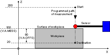
Measurement with coordinate preset G92:
%meas2
N05 #MEAS MODE[1]
N10 G92 Z33
N20 G01 G00 G90 Z200 F2000
N30 G100 Z20 F2000
N40 #MSG SYN["V.A.MESS.Z=%f", V.A.MESS.Z] -> V.A.MESS.Z = 100.0
N50 #MSG SYN["V.A.MOFFS.Z=%f", V.A.MOFFS.Z] -> V.A.MOFFS.Z = 47.0
N60 #MSG SYN["V.A.MEIN.Z=%f", V.A.MEIN.Z] -> V.A.MEIN.Z = 0.0
N70 G101 Z1
N80 #MSG SYN["V.A.MEIN.Z=%f", V.A.MEIN.Z] -> V.A.MEIN.Z = 47.0
N90 G01 Z100 F1000
N100 #MSG SYN["V.A.ABS.Z=%f", V.A.ABS.Z] -> V.A.ABS.Z = 180.0
N110 G102 Z1
N120 #MSG SYN["V.A.MEIN.Z=%f", V.A.MEIN.Z] -> V.A.MEIN.Z = 0.0
N130 G01 Z100 F1000
N140 #MSG SYN["V.A.ABS.Z=%f", V.A.ABS.Z] -> V.A.ABS.Z = 133.0
N150 M30 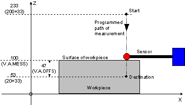
Measurement with machine coordinate system CS, shift:
%meas3
N05 #MEAS MODE[1]
N10 #CS ON[0,0,33,0,0,0]
N20 G01 G00 G90 Z200 F2000
N30 G100 Z20 F2000
N40 #MSG SYN["V.A.MESS.Z=%f", V.A.MESS.Z] -> V.A.MESS.Z = 67.0
N50 #MSG SYN["V.A.MOFFS.Z=%f", V.A.MOFFS.Z] -> V.A.MOFFS.Z = 47.0
N60 #MSG SYN["V.A.MEIN.Z=%f", V.A.MEIN.Z] -> V.A.MEIN.Z = 0.0
N70 G101 Z1
N80 #MSG SYN["V.A.MEIN.Z=%f", V.A.MEIN.Z] -> V.A.MEIN.Z = 47.0
N90 G01 Z100 F1000
N100 #MSG SYN["V.A.ABS.Z=%f", V.A.ABS.Z] -> V.A.ABS.Z = 147.0
N110 G102 Z1
N120 #MSG SYN["V.A.MEIN.Z=%f", V.A.MEIN.Z] -> V.A.MEIN.Z = 0.0
N130 G01 Z100 F1000
N140 #MSG SYN["V.A.ABS.Z=%f", V.A.ABS.Z] -> V.A.ABS.Z = 100.0
N150 #CS OFF
N160 M30 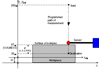
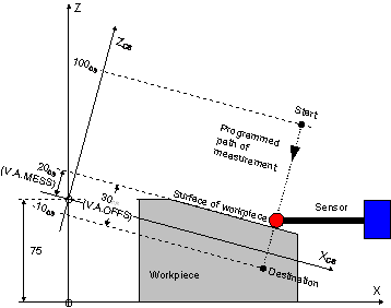
Measurement within machine coordinate system CS, shift and rotation:
Assumption: The measurement device is triggered at Z ACS-Position 55.5mm.
%meas4
N05 #MEAS MODE[1]
N10 #CS ON[0,0,75,0,15,0]
N20 G01 G00 G90 X150 Z100 F2000
N30 G100 Z-10 F1000
N40 #MSG SYN["V.A.MESS.Z=%f", V.A.MESS.Z] -> V.A.MESS.Z = 20.0
N50 #MSG SYN["V.A.MOFFS.Z=%f", V.A.MOFFS.Z] -> V.A.MOFFS.Z = 30.0
N60 #MSG SYN["V.A.MEIN.Z=%f", V.A.MEIN.Z] -> V.A.MEIN.Z = 0.0
N70 G101 Z1
N80 #MSG SYN["V.A.MEIN.Z=%f", V.A.MEIN.Z] -> V.A.MEIN.Z = 30.0
N90 G01 Z50 F1000
N100 #MSG SYN["V.A.ABS.Z=%f", V.A.ABS.Z] -> V.A.ABS.Z = 80.0
N110 G102 Z1
N120 #MSG SYN["V.A.MEIN.Z=%f", V.A.MEIN.Z] -> V.A.MEIN.Z = 0.0
N130 G01 Z50 F1000
N140 #MSG SYN["V.A.ABS.Z=%f", V.A.ABS.Z] -> V.A.ABS.Z = 50.0
N150 #CS OFF
N160 M30