Connecting the manual operating modules
Mounting
When mounting, observe the information in the chapter entitled Mounting rail installation.
- Ensure that the system is powered down and in a safe state.
- Install the first bus terminal block, consisting of the fieldbus coupler and the desired Bus Terminals, on a mounting rail.
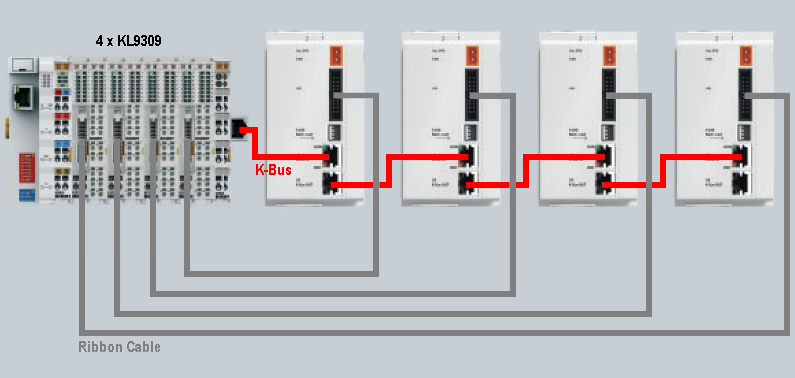
Instead of a standard end terminal (KL9010), install an end terminal with RJ45 socket (KL9020) as the last terminal at the end of the first Bus Terminal block. - Mount the first manual operating module.
- Plug the RJ45 plug of an Ethernet cable into the RJ45 socket of the KL85xx until it audibly engages.
Plug the other RJ45 plug of the Ethernet cable into the RJ45 socket of the KL85xx labelled IN until it audibly engages. - Mount the next manual operating module.
- Plug the RJ45 plug of the Ethernet cable into the RJ45 socket of the KL85xx labelled OUT of the previous manual operating module until it audibly engages.
Plug the other RJ45 plug of the Ethernet cable into the RJ45 socket of the KL85xx labelled IN of the added manual operating module until it audibly engages. - Repeat steps 5 and 6 in order to connect further expansion terminal blocks. A maximum of 31 expansion terminal blocks can be connected.
- Set the Function Switch on all Coupler Terminals (KL85xx/KL9050) correctly.
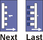
Function Switch
Activate the terminating resistor at the last expansion terminal block of your K-bus extension system by switching the Function Switch on the last Coupler Terminal (KL85xx/KL9050) to the Last position.
| |
Correct setting of the Function Switch Correct setting of the Function Switches of all Coupler Terminals (KL9050) within a K-bus extension system must be ensured: The Function Switch of all Coupler Terminals (KL85xx/KL9050) to which a continuing Ethernet cable is connected must be set to position Next! (see image below) The Function Switch may be set to the Last position only at the last Coupler Terminal (KL85xx/KL9050) of the K-bus extension system! (see image below) All expansion terminal blocks connected after a Coupler Terminal (KL85xx/KL9050), whose Function Switch is set to position Last, are not included correctly in the process image: Correct setting of the Function Switches must also be ensured if Coupler Terminals (KL85xx/KL9050) are replaced! |

Disassembly
When removing, observe the information in the chapter entitled Mounting rail installation.
- Ensure that the system is powered down and in a safe state.
- Press the plastic lock of the RJ45 plug and pull it from the socket.
- Carefully pull the orange-colored strap approximately 1 cm out of the terminal to be disassembled, until it protrudes loosely. The lock with the mounting rail is now released for this terminal, and the terminal can be pulled from the mounting rail without excessive force.
- Grasp the released terminal with thumb and index finger simultaneous at the upper and lower grooved housing surfaces and pull the terminal away from the mounting rail.