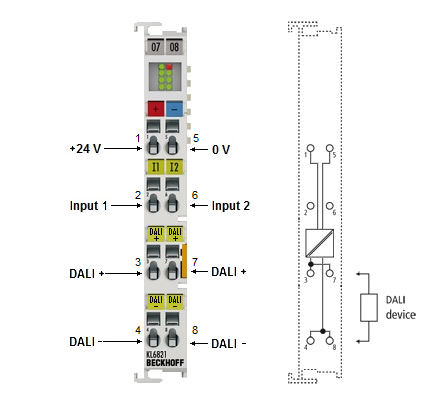
Contact assignment
| |
Risk of injury through electric shock and damage to the device! Bring the bus terminal system into a safe, de-energized state before starting mounting, disassembly or wiring of the bus terminals! |

Contact assignment
Terminal point | No. | Connection for |
|---|---|---|
+24 V DALI + | 1 | Power supply connection +24 V |
Input 1 | 2 | Digital input 1 |
DALI + | 3 | DALI-2 bus + (internally connected to terminal point 7) |
DALI - | 4 | DALI-2 bus - (internally connected to terminal point 8) |
0 V | 5 | Power supply connection 0 V |
Input 2 | 6 | Digital input 2 |
DALI + | 7 | DALI-2 bus + (internally connected to terminal point 3) |
DALI - | 8 | DALI-2 bus - (internally connected to terminal point 4) |
Input 1 and input 2 (terminal point 2 and 6)
The digital Input 1 and Input 2 only work if the supply voltage (24 V) is present and the K-bus is supplied with voltage.
The digital Input 1 and Input 2 have priority over automatic control through the PLC program. If the digital inputs are operated, other PLC-controlled DALI commands are blocked. To enable them a positive edge is required at the bResetInactiveProcessImage input of the function block FB_KL6821Communication. See documentation TwinCAT 3 | PLC library: Tc3_DALI. Alternatively, the priority rule can also be changed by setting it with the KS2000 configuration software (do not lock process image).
The behavior of the digital inputs DI1 and DI2 can be changed via the library function blocks or with the KS2000 configuration software. To support commissioning, the following default behavior is assigned in the delivered state.
Signal | Broadcast DALI command | Action | Comment |
|---|---|---|---|
Rising edge at DI1 | 00hex | Turns OFF all control gears (without fading). | Factory setting |
Rising edge at DI2 | 05hex | Switches all control gears to maximum brightness. If a control gear is switched off, it is switched on. | Factory setting |
Cable lengths in DALI mode
The DALI bus can be configured in a line or star topology, or in a mix of the two. The maximum cable length must not exceed 300 m!
Cable length | Wire cross-section |
|---|---|
up to 100 m | min. 0.5 mm2 |
up to 150 m | min. 0.75 mm2 |
up to 300 m | min. 1.5 mm2 |
Further important boundary conditions derived from IEC 62386:
- The DALI cables must not be terminated with resistors.
- The maximum voltage drop between the sender and the receiver must not exceed 2 V.
- If the maximum cable length is utilized, it is not advisable to lay DALI in combination with the power cable.