Contact assignment and LEDs
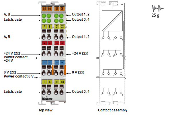
Contact assignment
Terminal points - left part of the housing
Terminal point | No. | Contact for |
|---|---|---|
A | 1 | Sensor input A (incremental encoder or pulse generator) |
+24 V | 2 | +24 V supply voltage e. g. for encoder |
0 V | 3 | 0 V supply voltage e. g. for encoder |
Latch | 4 | Latch input |
B | 5 | Sensor input B (incremental encoder or pulse generator) |
+24 V | 6 | +24 V supply voltage e. g. for encoder |
0 V | 7 | 0 V supply voltage e. g. for encoder |
Gate | 8 | Gate input |
Terminal points- right part of the housing
Terminal point | No. | Contact for |
|---|---|---|
Output 1 | 1' | Switch output 1 |
+24 V | 2' | +24 V supply voltage e. g. for encoder |
0 V | 3' | 0 V supply voltage e. g. for encoder |
Output 3 | 4' | Switch output 3 |
Output 2 | 5' | Switch output 2 |
+24 V | 6' | +24 V supply voltage e. g. for encoder |
0 V | 7' | 0 V supply voltage e. g. for encoder |
Output 4 | 8' | Switch output 4 |
LED display
LED | Color | Description | |
|---|---|---|---|
A | green | on | Input active |
B | green | on | Input active |
Latch | green | on | Latch input active |
Gate | green | on | Gate input active |
Output 1 | green | on | Output 1 active |
Output 2 | green | on | Output 2 active |
Output 3 | green | on | Output 3 active |
Output 4 | green | on | Output 4 active |