KL5111 –Terminal configuration
The terminal can be configured and parameterized via the internal register structure.
Each terminal channel is mapped in the Bus Coupler. Depending on the type of the Bus Coupler and the mapping configuration (e.g. Motorola/Intel format, word alignment etc.) the terminal data are mapped in different ways to the Bus Coupler memory.
In contrast to analog input and output terminals, the KL5111 always also maps the control and status byte, independently of the higher-level fieldbus system.
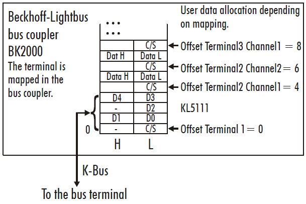
BK2000 Lightbus Coupler
With the BK2000 Lightbus coupler, the control/status byte is always mapped in addition to the data bytes (i.e. for all analog terminals). This is always in the low byte on the offset address of the terminal channel.
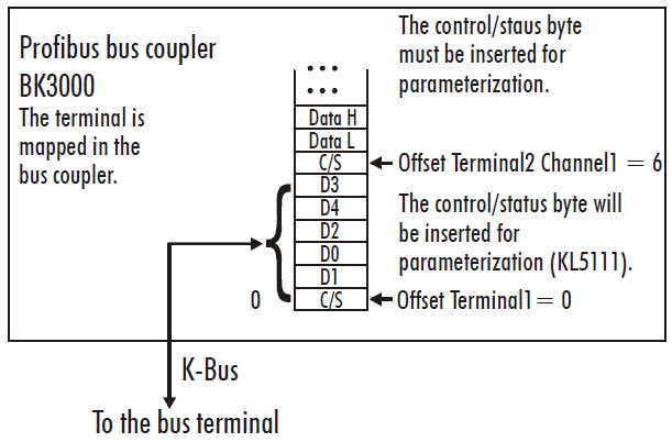
BK3000 PROFIBUS coupler
In the BK3000 Profibus Coupler, the KL5111 is always mapped with 6 bytes of input data and 6 bytes of output data.
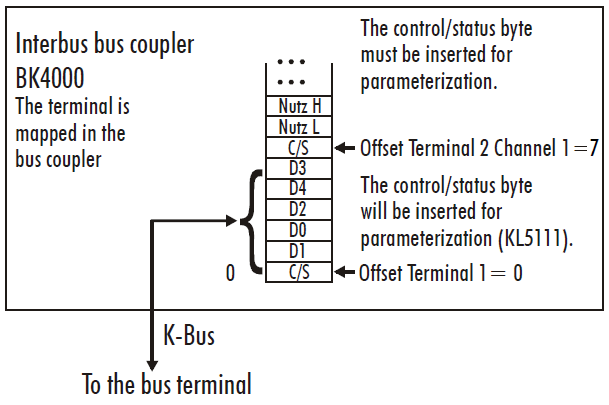
BK4000 Interbus Coupler
The BK4000 Interbus Coupler normally maps the KL5111 with 6 bytes of input data and 6 bytes of output data.
Other Bus Couplers and further information
Further information about the mapping configuration of Bus Couplers can be found in the Appendix of the respective Bus Coupler manual under Master configuration.
The chapter on Mapping in the Bus Coupler contains an overview of possible mapping configurations, depending on the configurable parameters.
 | Parameterization with KS2000 The KS2000 configuration software can be used for parameterizations via the serial interface of the Bus Coupler, independent of the fieldbus system. |