Contact assignment and LEDs
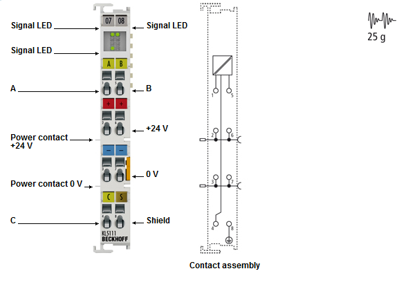
KL5111/KS5111 - Contact assignment
Terminal point | No. | Contact for | |
|---|---|---|---|
A | 1 | Count input, the positive edges of the input pulses are counted | |
+24 V | 2 | +24 V supply voltage for encoder | |
0 V | 3 | 0 V supply voltage for encoder | |
C | 4 | Gate input | C=0: counter enabled |
C=1: counter locked | |||
B | 5 | Up/down input | B=0: up count direction |
B=1: down count direction | |||
+24 V | 6 | +24 V supply voltage for encoder | |
0 V | 7 | 0 V supply voltage for encoder | |
Shield | 8 | Shield connector | |
KL5111/KS5111 - LED display
LED | Color | Description | |
|---|---|---|---|
A | green | On | Count input active |
B | green | Off | Up/down input not active (up count direction) |
On | Up/down input active (down count direction) | ||
C | green | Off | Gate input not active (counter enabled) |
On | Gate input active (counter locked) | ||