Basic Function Principles
The KL5101 incremental encoder interface terminal enables the connection of any incremental encoder to the Bus Coupler or PLC. A 16-bit counter with a quadrature decoder and a 16-bit latch can be read, set or enabled. In addition to the encoder inputs A, B and C, an additional latch input G1 (24 V) and a gate input G2 (24 V) for locking the counter are available.
It is also possible for the 16-bit up/down counter operating mode to be selected. In this mode, input B is the counter input.
1, 2, or 4-fold evaluation of the encoder signals A, B, C in simple or complementary form can be parameterized via the fieldbus.
The terminal is supplied as a 4-fold quadrature decoder with complementary evaluation of the sensor signals A, B, C. To operate the encoder interface, the 24 VDC operating voltage must be connected to the terminal contacts in addition to the encoder inputs.
From hardware version 03 (i.e. from 18 June 1998) the KL5101 is delivered with new, additional features:
- If the incremental encoder has an alarm output, it can be connected to the status input of the KL5101.
- A period duration measurement with a resolution of 200 ns can also be carried out.
Operation modes
Can be set via the feature register (default setting incremental encoder):
A, B, zero pulse incremental encoder (default)
Up/down counter with:
- A = count; the positive edges of the input pulses are counted
- B = up/down input
- B = 0: Up count direction
- B = 1: Down count direction
- C = gate input
- C = 0: Counter enabled
- C = 1: Counter is locked
Functions
- Counting
- Set counter
- Activate zero pulse and save valid value
- Determination of the period duration between two pulses with a resolution of 200 ns (the time between two positive edges of input signal A is evaluated).
- Display of a counter overflow or underflow.
Process data
The KL5101 always occupies 6 bytes of input data and 6 bytes of output data. The control/status byte is located at the lowest byte offset. The data word D0/D1 contains the counter word (read/set), the data word D3/D4 contains the latch word (read). In period duration measurement mode, the period duration is output in D2 together with D3/D4.
LED display
The signal LEDs indicate the states of the encoder inputs A, B, C and the status input, as well as the state of the logic inputs of the gate and the additional external latch. The RUN LED indicates cyclic data exchange with the higher-level controller. If no process data is exchanged for 100 ms, the RUN LED goes out. The Power UE LED indicates the operating voltage for the power supply of the incremental encoder.
Contact assignment
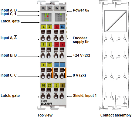
- Inputs A, /A: Pulse input in encoder and counter mode of the terminal.
- Inputs B, /B: Phase-shifted pulse input in encoder mode of the terminal.
- Counting direction input in counter mode of the terminal: Counting direction:
- + 5 V (or open contact): up
- 0 V: down
- Inputs C, /C: Zero point pulse input for the terminal’s latch register.
This input is activated via the EN_LATC bit in the control byte of the terminal. - External Latch 24 V: Additional latch input of the terminal.
This input is activated via the EN_LAT_EXT bit in the control byte of the terminal.
If this input is enabled, the counter value will be latched when the edge changes from 0 V to 24 V. - External Gate 24 V: A high level at this contact suppresses counting by the terminal.
- Status Input: If the incremental encoder has an alarm output, it can be connected to the status input (active low input with internal pull-up circuitry).
- Ue: Power supply for the encoder (+5 V).
- Uo: Power supply for the encoder (0 V).
- 0 V, 24 V: A voltage supply of 0 V and 24 V must be connected to these contacts for operation of the terminal.