Contact assignment and LEDs
| |
Risk of injury through electric shock and damage to the device! Bring the Bus Terminals system into a safe, de-energized state before starting mounting, disassembly or wiring of the Bus Terminals! |

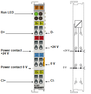
KL5001/KS5001 - Contact assignment
Terminal point | No. | Comment |
|---|---|---|
D+ | 1 | SSI data input D+ |
+24 V | 2 | +24 V (internally connected to terminal point 6 and positive power contact) |
0 V | 3 | 0 V (internally connected to terminal point 7 and negative power contact) |
Cl+ | 4 | Clock output CL+ |
D- | 5 | SSI data input D- |
+24 V | 6 | +24 V (internally connected to terminal point 2 and positive power contact) |
0 V | 7 | 0 V (internally connected to terminal point 3 and negative power contact) |
Cl- | 8 | Clock output CL- |
KL5001/KS5001 - LED display
LED | Color | Description | |
|---|---|---|---|
Run1 LED | green | On: | Normal operation |
Off: | Watchdog timer overflow has occurred. If no process data is transmitted to the bus coupler for 100 ms, the green LED goes out. | ||