KL/KS4001, KL/KS4002 - Contact assignm. and LEDs
| |
Risk of injury through electric shock and damage to the device! Bring the Bus Terminals system into a safe, de-energized state before starting mounting, disassembly or wiring of the Bus Terminals! |

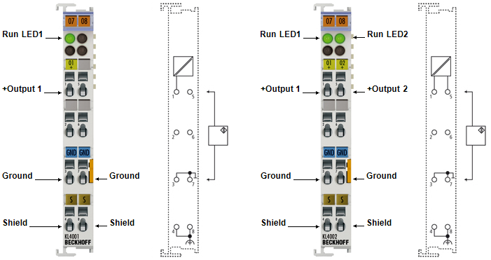
KL4001/KS4001 Contact assignment | ||
|---|---|---|
Terminal point | No. | Comment |
Output | 1 | + Output 1 |
n.c. | 2 | not used |
GND | 3 | Internal ground (internally connected to terminal point 7) |
Shield | 4 | PE contact (internally connected to terminal point 8) |
n.c. | 5 | not used |
n.c. | 6 | not used |
GND | 7 | Internal ground (internally connected to terminal point 3) |
Shield | 8 | PE contact (internally connected to terminal point 4) |
KL4002/KS4002- Contact assignment | ||
|---|---|---|
Terminal point | No. | Comment |
Output 1 | 1 | + Output 1 |
n.c. | 2 | not used |
GND | 3 | Internal ground (internally connected to terminal point 7) |
Shield | 4 | PE contact (internally connected to terminal point 8) |
Output 2 | 5 | + Output 2 |
n.c. | 6 | not used |
GND | 7 | Internal ground (internally connected to terminal point 3) |
Shield | 8 | PE contact (internally connected to terminal point 4) |
LED description | |||
|---|---|---|---|
LED | Color | Description | |
Run1 LED | green | On: | Normal operation |
Off: | Watchdog timer overflow has occurred. If no process data is transmitted to the bus coupler for 100 ms, the green LEDs go out. The output assumes a user-specified voltage (see Feature register). | ||