Process data
Calculation of process data
The process data are calculated in up to seven steps between reading of the ADC and the process data output.
Designation | Calculation formula | not active |
|---|---|---|
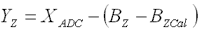
Offset correction |
|
|
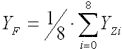
Filter for averaging over 8 values |
|
|
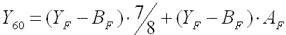
60 Hz mode adaptation |
|
|
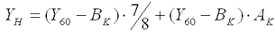
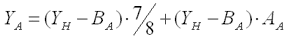
Calibration active |
|
|
|
| |
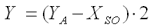
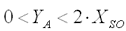
AC system offset |
|
|
Scaling |
| - |


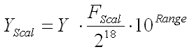
The scaling includes the powers of ten selected in the range.
All gain factors should therefore correspond to 1/8 in order to obtain a total factor of 1. The value 8192 (0x2000) results in a total factor of 1.
Designation | Meaning | Register | Designation | Meaning | Register |
|---|---|---|---|---|---|
XADC | Output value of the A/D converter |
|
|
| |
YZ | Measured value after ADC offset correction |
| BZ | Current ADC Zero value |
|
BZCal | ADC Zero at the time of calibration |
| |||
YF | Measured value after averaging |
|
|
|
|
Y60 | Measured value after adaptation of the 60 Hz integration time |
| BF | 60 Hz offset |
|
AF | 60 Hz gain |
| |||
YH | Measured value after manufacturer calibration |
| BK | Manufacturer offset |
|
AK | Manufacturer gain |
| |||
YA | Measured value after user calibration |
| BA | User offset |
|
AA | User gain |
| |||
Y | Measured value after AC system offset |
| XSO | AC system offset |
|
YScal | Measured value after scaling |
| FScal | End value in 1 bit per 1µV / 1µA |
|
Determining (user) gain values
The terminal has one user compensation value pair for each measuring range and measurement type, i.e. 14 pairs in total. "+1" (0x4000) is not used in order to increase the resolution of the gain value.
Since the gain values may be less than 1, a factor of 1/8 is multiplied to the gain value. For a gain of 1 the gain value must be 0x2000.
For gain G = 1 the following applies:
For other values G must be replaced with the required gain factor.
Before the compensation the value display option should be set to "right-aligned": Register R32.12 to R32.15 value assignment of 1dec.