Technology
General description
The functionality of the KL3681 is similar to that of a commercial digital multimeter. The terminal offers the following features:
- Single-channel measurement
- AC/DC voltage measurement, range selection automatic through Autorange function or through the controller; measuring ranges 300 mV, 3 V, 30 V, 300 V
- AC/DC current measurement in the 1 A path (internal fuse: 1.25 A) or 10 A path (no internal fuse), measuring ranges: 100 mA, 1 A, 10 A
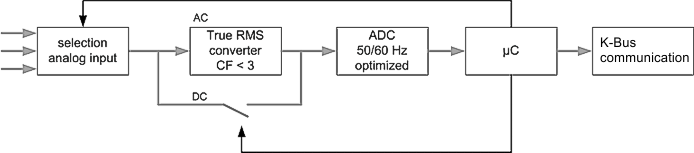
- Formation of measured values:
AC current/voltage is calculated as a true RMS value without DC component, an integration of the signal waveform in the ADC takes place
DC current/voltage is calculated as an arithmetic mean value, an integration of the signal waveform in the ADC takes place - Electrical isolation from the fieldbus
- Very good interference immunity through dual-slope conversion technique
- Display of measurement type (current/voltage) and overload through LED
- Typical update rate approx. 2/s, after measuring range change up to approx. 1/s, with deactivated filter approx. 16/s.
The data collection is shown in fig. KL3681 - Data flow.
Application note
For the measurement of a 60 Hz signal, the register R32.7 should be set accordingly. For all other signal frequencies the 50 Hz preset is valid, because of the longer integration time. The accuracy information shown below refer to a input signal of a frequency range of > 0 ... 1 kHz. With higher frequencies the measurement accuracy decreases (-3 dB > 500 kHz).
It is possible to measure a non-sinus AC input signal if the Crest factor is < 3. The accuracy information below refers to a Crest factor of max. 2.
The simultaneous electrical connection of both current paths (10, 1 A) and the voltage path for a following alternating measurement of values is possible, but not recommended. In case of AC components in the signal, a parasitic crosstalk from path to path can occur. After switching over, the process data update time can be up to 1 second.
Specifications
Accuracy
The unused measurement input should be connected to the COM port of the terminal in order to make the analysis as accurate as possible and minimize interference.
- Possible measuring inputs at the terminal:
- Voltage measurement 300 mV – 300 V (connection points 1 + 5)
- Current measurement 100 mA – 1 A (connection point 7)
- Current measurement 10 A (connection point 3)
The measuring accuracy depends on the type of signal to be measures and on the terminal settings.
The accuracy values specified in the following table apply to the default settings for the terminal parameters:
- Enable vendor calibration: | true |
- Enable filter: | true |
- Frequency: | 50 Hz |
- Zero compensation interval: | Off (0) |
- Presentation: | Scaled (1Bit/1µV) (2) |
Measuring tolerances depending on temperatures. MBE = full scale value
Signal to be measured | Typical max. tolerance in % of full scale value1) | Typical temperature drift2)6) | ||
|---|---|---|---|---|
Measurement type | Measuring range | 40°C 3) | 0 ... 55°C | ppm/°C |
DC | 3 V - 300 V 8) | 0.01 | 0.2 | 35 |
300 mV 8) | 0.05 | 0.2 | 35 | |
100 mA 7) | 0.1 | 0.5 | 50 | |
1 A | 0.1 | 0.5 | 50 | |
10 A | 0.2 | 1.2 | 170 | |
AC 4) 5) | 3 V - 300 V | 0.25 | 0.75 | 130 |
300 mV | 0.25 | 0.5 | 50 | |
100 mA | 0.5 | 1 | 50 | |
1 A | 0.5 | 0.7 | 50 | |
10 A | 0.5 | 1.2 | 150 | |
1) In 60 Hz mode of ADC 0.02 should be added to the specified tolerance
2) The values apply to a minimum terminal warm-up time of 30 minutes
3) The compensation temperature is 40 °C
4) All AC voltage and current ranges are specified for a range of 5% to 100%
5) Crest factor < 2
6) In 60 Hz mode an additional temperature drift of 20 ppm/°C is to be expected.
7) The maximum deviation under EMC test conditions according to IEC 61131 is 1 %
8) The maximum deviation under EMC test conditions according to IEC 61131 is 0.2 %
Measuring procedure
The measuring technique in the terminal is based on the dual-slope technique.
The Zero Offset Compensation function reads the internal ADC offset and corrects the analog value accordingly. The additional temperature drift can thus be partly compensated, either cyclically or through external control.
Operating conditions
- To avoid interference shielded cables must be used for the analog signals. The maximum cable length is 30 m.
- For DC voltage measurements may the AC component may not exceed 150 Vpp.
- For AC voltage measurements may the DC component may not exceed 150 V (sine voltage).
- The peak voltage (relative to the COM terminal) may not exceed 600 V.
Internal resistances
Measurement type | Measuring range | Internal resistance |
|---|---|---|
DC | 300 mV - 300 V | 12.5 MΩ |
100 mA - 1 A | 0.2 Ω | |
10 A | 3 mΩ | |
AC 4) 5) | 300 mV - 300 V | 1 MΩ, approx. 33 pF |
100 mA - 1 A | 0.2 Ω | |
10 A | 3 mΩ |
Default Setting
The factory setting for the multimeter terminal enables voltages up to 300 VDC to be measured directly without additional settings. The Autorange function is active and selects the measuring range automatically. The measured value is displayed with 1 bit/µV, i.e. no adjustment is required.