Measuring error due to input overload
The various variants of the KL3403 differ only in terms of input configuration. The output value for the nominal value (full scale) is the same for most variants (see process data).
Terminal type | KL3403-... | |||||||
0000 | 0010 | 0014* | 0020 | 0022** | 0025 | 0026 | 0333 | |
Nominal value | 1 A | 5 A | 60 mV | 20 mA | 20 mA | 250 mA | 1 A | 333 mV |
Output for RMS value at nominal value | 1000dec | 1000dec | 25000dec | 1000dec | 4000dec | 1000dec | 1000dec | 1000dec |
*) for KL3403-0014: three additional voltage circuits instead of the current circuits: 60 mV for connection of external shunts
**) for KL3403-0022: three additional current circuits instead of the voltage circuits: also 20 mA
Current and sampling curve for input signals within the permitted measuring range
If the current input values are within the permitted range, i.e. not above the rated current for the terminal, a valid measured value (≤ 1414dec) is read for each interpolation point.
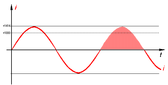 Fig.29: Current and sampling curve for input signals within the permitted measuring range
In the example shown (full scale), the terminal outputs the value 1000dec for the RMS value of the current.
Current and sampling curve for 20% overload
If the input current exceeds the rated terminal current, the terminal also outputs the value 1414dec for the peak values (which are greater than the rated current times root 2). For this interpolation points a measuring error occurs due to input overload.
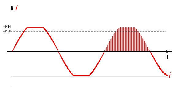 Fig.30: Current and sampling curve for 20% overload
In the example shown, the terminal outputs a value of approx. 1150dec for the RMS value of the current. This value is already subject to a small error.
Current and sampling curve for 50% overload
The higher the input overload, the more interpolation points are subject to an ever greater measuring error due to the input overload.
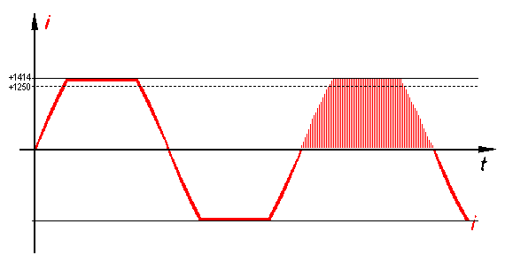 Fig.31: Current and sampling curve for 50% overload
In the example shown, the terminal outputs a value of approx. 1250dec for the RMS value of the current. This value is subject to a relevant error.
The measuring error increases with the degree of overload
With increasing overload, the RMS value "I" calculated from the interpolation points still increases with the input voltage "î", but it no longer increased linearly with the input signal, and the measuring error "∆" increases quickly!
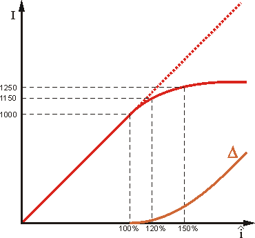 Fig.32: Increase in measuring error "∆" with increasing overload
The output values indicated for input overloads of 20% and 50% are typical values. They may differ to some degree, due to component tolerances between terminals.