Power measurement
Active power measurement
The KL3403 measures the active power P according to the following equation
P: Active power
n: number of samples (64000 samples / s)
u(t): Instantaneous voltage value
i(t): instantaneous current value
Power s(t) curve
 Fig.4: Power s(t) curve
In the first step, the power s(t) is calculated at each sampling instant:
The mean value over the measuring interval is calculated. Here too, the correct choice of the intervals is important, as described in section RMS value measurement (the interval can only be changed simultaneously for U, I and P).
The power frequency is twice that of the corresponding voltages and currents.
Apparent power measurement
In real networks, not all consumers are purely ohmic. Phase shifts occur between current and voltage. This does not affect the methodology for determining the rms values of voltage and current as described above.
The situation for the active power is different: Here, the product of effective voltage and effective current is the apparent power.
The active power is smaller than the apparent power.
S: Apparent power
P: Active power
Q: Reactive power
φ: Phase shift angle
u(t), i(t), p(t) curves with phase shift angle φ
 Fig.5: u(t), i(t), p(t) curves with phase shift angle φ
In this context, further parameters of the mains system and its consumers are significant:
- apparent power S
- reactive power Q
- power factor cos φ
The KL3403 determines the following values:
- active power P
- effective voltage U
- effective current I
From these values, the required parameters can be calculated:
- apparent power:
-
- reactive power:
- Power factor:
Sign for power measurement
The sign of the active power P and of the power factor cos φ provide about information the direction of the energy flow. A positive sign indicates the motor mode, a negative sign indicates generator mode.
In addition, the sign of the reactive power Q indicates the direction of the phase shift between current and voltage. The diagram Four-quadrant representation of active/reactive power in motor and generator mode illustrates this. In motor mode (quadrant I & IV) a positive reactive power indicates an inductive load, a negative reactive power indicates a capacitive load. In generator mode (quadrant II & III), an inductive acting generator is indicated by a positive reactive power, a capacitive acting generator by a negative reactive power.
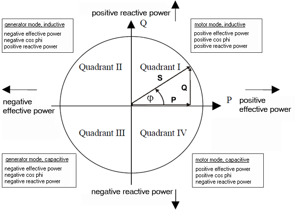 Fig.6: Four-quadrant representation of active/reactive power in motor and generator mode