Connecting the KL3362
 WARNING
Risk of injury through electric shock and damage to the device!
Bring the Bus Terminals system into a safe, de-energized state before starting mounting, disassembly or wiring of the Bus Terminals.
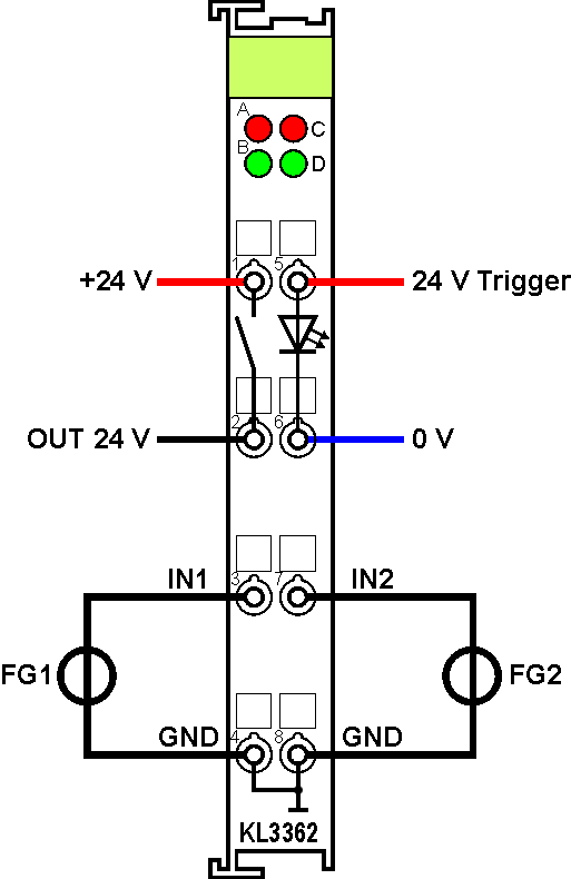
The diagram shows the connection of two function generators (FG1, FG2) to the channels of the KL3362 oscilloscope terminal.
Terminal point | No. | Connection |
|---|---|---|
+ 24V | 1 | Supply voltage for digital output |
OUT 24V | 2 | Digital output |
IN 1 | 3 | Oscilloscope input channel 1 ( -10 V to +10 V) |
GND | 4 | Ground for oscilloscope input channel 1 (internally connected with terminal no. 8) |
24V Trigger | 5 | Trigger input |
0V | 6 | Ground for trigger input |
IN 2 | 7 | Oscilloscope input channel 2 ( -10 V to +10 V) |
GND | 8 | Ground for oscilloscope input channel 2 (internally connected with terminal no. 4) |