Connecting the KL3361
 WARNING
Bring the Bus Terminals system into a safe, de-energized state before starting mounting, disassembly or wiring of the Bus Terminals.
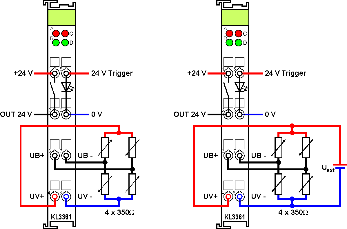
The diagram shows the connection of four strain gauges (SG) as a bridge circuit, with supply of the measuring bridge
- through the oscilloscope terminal (left) or
- from an external voltage source Uext (right).
Terminal point | No. | Connection |
|---|---|---|
+ 24 V | 1 | Supply voltage for digital output |
OUT 24 V | 2 | Digital output |
UB+ | 3 | Input for differential voltage of the measuring bridge |
UV+ | 4 | 5 V supply voltage for the strain gauges in a bridge circuit or |
24 V Trigger | 5 | Trigger input |
0V | 6 | Ground for trigger input |
UB- | 7 | Input for differential voltage of the measuring bridge |
UV- | 8 | 0 V supply voltage for the strain gauges in a bridge circuit or |
Supply of the measuring bridge via KL3361
The total resistance of the measuring bridge should be dimensioned in such a way that the current to be supplied by the oscilloscope terminal at the terminals UV+ and UV- never exceeds 20 mA.
Supply of the measuring bridge from an external voltage source
Note the following if the measuring bridge is supplied from an external voltage source:
The external supply voltage
- must also be applied to the UV+ and UV- connections for reference;
- must be within the range +5 V to +10 V;
- must not vary by more than ±5% during operation.
Fluctuations of the external supply voltage increase the measurement error!
After changing the external supply voltage, the oscilloscope terminal has to be restarted for re-balancing!
The internal voltage source switches off automatically, as soon as an external voltage of more than 5 V is applied to the UV+ and UV- terminals of the oscilloscope terminal.