Contact assignment and LED description
| |
Risk of injury through electric shock and damage to the device! Bring the Bus Terminal system into a safe, voltage-free state before starting mounting, disassembly or wiring of the Bus Terminals! |

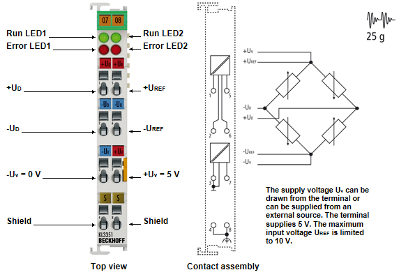
Contact assignment
Terminal point | No. | Comment |
|---|---|---|
+UD | 1 | + input measuring voltage |
-UD | 2 | - input measuring voltage |
-UV | 3 | 0 V (supply voltage) |
Shield | 4 | Shield |
+Uref | 5 | + input reference voltage |
-Utef | 6 | - input reference voltage |
+UV | 7 | +5 V (supply voltage) |
Shield | 8 | Shield |
LED description
LED | Color | Description |
|---|---|---|
Run LED1 | green | On: Normal operation Off: Watchdog timer overflow has occurred. If no process data is transmitted to the Bus Coupler for 100 ms, the green LEDs go out |
Error LED1 | red | outside the range for the signal voltage (UD) or wire breakage |
Error LED2 | red | outside the acceptable range for the reference voltage (Uref) |